background image

128-9108

7 of 24

Page 7

White Wire:

 Parking Light Flasher Output

This wire is the normally open contact of the on board parking light flasher relay.  Connect
this wire to the vehicle parking light feed wire.

7 Pin Accessory Input/Output Harness, Connector (P/N 4120107)

Brown/Red Wire:  

Brake Positive Inhibit Input

The Brown/Red wire provides an instant shutdown for the Remote Start Control module
whenever it gets + 12 volts.  If the Brake lights switch in the vehicle sw 12 volts to
the brake light circuit, connect the Brown/Red wire to the output side of the brake switch.
This will allow the Remote Start to shut down if an attempt is made to operate the vehicle
without the key while running under the control of the Remote Start.  In most vehicles, in
order to shift into gear, the brake pedal must be depressed.  The brake input will in turn
cause the remote start unit to shut off.

Gray Wire:  

Negative Inhibit Input

The Gray wire provides an instant shutdown for the Remote Start Control Module whenever
it is grounded.  Connect the gray wire to the hood pin switch previously installed.
This wire must be routed through a grommet in the firewall and connected to the hood pin
switch.  If the pin switch is to be used with an alarm system, connect this wire using a diode
assembly.

WARNING: DO NOT RELEASE THIS VEHICLE TO THE CONSUMER UNTIL YOU
CONFIRM THE OPERATION OF THE HOOD PIN SAFETY SHUT DOWN FEATURE.
IMPORTANT!

 This connection is a safety wire and must be connected to a hood pin switch

and tested as described.  Failure to do so may result in personal injury or property damage.
This wire may also be used if the vehicle brake light circuit switches ground to the brake
lights.  An isolation diode must be used for ground switched brake light circuits and must be
connected to the output of the brake switch.
To test this circuit, while the vehicle is running under control of the remote start unit, open
the vehicle’s hood.  The remote start unit should shut down immediately. If not, check the
wiring to the control module and the under hood pin switch.

WARNING: DO NOT RELEASE THE VEHICLE TO THE CONSUMER IF THIS CIRCUIT
DOES NOT PERFORM AS SPECIFIED.

Purple/White Wire: 

Tachometer Input Signal

This wire will continually monitor the engine's tach rate while the unit is under power of
the Remote Start module.  Route this wire to the vehicle ECM tach input or through the
firewall into the engine compartment and connect to the negative side of the ignition coil.
This Remote Start unit learns the tach rate of the vehicle and in most cases will operate
properly from one multi coil pack regardless of the number of cylinders.
If the vehicle has a single coil unit for each cylinder, it may be necessary to connect to
one of the vehicles electronic fuel injector wires for proper RPM signal.

Red/White Wire:  

Delayed 250mA Pulsed  Channel 3 Output

The Red/White wire supplies a 250mA ground pulsed output whenever channel three of the
receiver is accessed.  Pressing the pre-programmed transmitter button for three seconds
will access this feature.  This is a low current output and must be connected to a relay to
supply power to the trunk release or the circuit you wish to control.  Connect the Red/White
wire to terminal # 86 of a VF45F11 P&B relay or equivalent.  Connect terminal  # 85  of the

Summary of Contents for PA-620C

Page 1: ...put With Selectable Duration Selectable RF Start Chirp Car Finder Mode Can elect to have horn beep along with parking lights if connected Selectable Run Times 5 10 15 or 20 Minutes Selectable Gas or Diesel Pathway Illumination Selectable On Arm On Disarm On Both or Off Automatic Start Timer Can be set to start your car automatically at 2 or 4 hour intervals 4 Negative Pulsed Aux Outputs Before Sta...

Page 2: ...to pinch the cable as this will cause poor or no RF reception to the control module Connect the 5 pin cable to the mating connector of control module HOOD PIN SWITCH P N 1363699 The pin switch included in this package is intended for protecting the hood area of the vehicle In all cases the switch must be mounted to a grounded metal surface When the pin switch is activated hood trunk open it will s...

Page 3: ...ealize why the connection of the safety wire is required for all mechanical switch con figurations WARNING Failure to make this connection properly can result in personal injury and property damage In all installations it is the responsibility of the installing technician to test the remote start unit and ensure that the vehicle cannot start via RF control in any gear selection other than park or ...

Page 4: ...onfirm that the factory relays in your particular vehicle do not exceed the rated 250mA output of the units door lock unlock circuit Plug the 2 pin connector of the door lock unlock harness into the mating connector shell of the control module Determine the door lock circuit of the vehicle you are working on and wire according to the diagrams shown 3 Wire Negative Switched Door Lock Circuits In th...

Page 5: ...128 9108 5 of 24 Page 5 ...

Page 6: ...ulsed ground output after the remote start unit shuts down and the G W R O P turns off This output will occur regardless of whether the circuit times out or is manually terminated Typically this output will be used to re lock the vehicle doors if the doors unlock automatically when the ignition circuit transitions to off Black Yellow Trace Wire Ground Output During Start Crank The Black Yellow wir...

Page 7: ...ult in personal injury or property damage This wire may also be used if the vehicle brake light circuit switches ground to the brake lights An isolation diode must be used for ground switched brake light circuits and must be connected to the output of the brake switch To test this circuit while the vehicle is running under control of the remote start unit open the vehicle s hood The remote start u...

Page 8: ...es a continuous pulsed output whenever the alarm or car finder feature is active This wire should be con nected to an external relay and wired to the vehicles interior entry lighting whenever the optional feature is desired Programming Tach Rate NOTE All applications require that tach be programmed The unit will not operate unless tach is programmed If an attempt is made to start the vehicle via t...

Page 9: ... 1 Dbl 1 1S L 350mS ul 1S 1S 2nd Accy Lock Auto Lock On Auto Lock Off Auto Lock Off 3rdAccy UL Auto UL On Auto UL Off Auto UL Off 4th Horn Chirp 10mS 16mS 30mS 40mS 50mS 16mS 5th Chp Del TX On Off Off 6th Park Lights Normal On 15 Sec On 15 Sec On 15 Sec Normal With Lock With U L w L U L When finished setting the keyless alarm selectable features turn the ignition off then on to advance to Bank 3 R...

Page 10: ...i cally exit the diagnostic mode The parking lights will flash a number of times indicating the reason for the last remote start shutdown The light flash indications are as follows 1 Flash Run timer expired 2 Flashes Low or no tach signal RPM 3 Flashes Positive inhibit wire activation 5 Flashes RF shutdown signal received or manual start trigger wire reactivated 6 Flashes High tach signal RPM 7 Fl...

Page 11: ...ce with cable ties or screws Be certain that the chosen mounting location will not inhibit any of the controls of the vehicle 2 Securely harness and tie all wiring up and away from all hot and moving parts that they may come in contact with under the dash board or in the engine compartment areas CAUTION Particularly avoid the area around the steering shaft and column as wires can wrap around these...

Page 12: ...128 9108 12 of 24 Page 12 2012 Audiovox Electronics Corporation Hauppauge NY 11788 128 9108 For technical support go to www prestigecarsecurity com or call 1 800 225 6074 ...

Page 13: ...la salida bloquear desbloquear de puerta seleccionable Safe Start requiere doble pulsación del botón start para activar la función de arranque remoto A bordo relé de luces de estacionamiento Tronco versión salida Claxon Chirp salida con duración seleccionable Seleccionable RF Inicio Chirp Car Finder modo puede elegir tener cuerno junto con las luces de estacionamiento si conecta una señal sonora S...

Page 14: ... pueden aflojar su superficie engomada Dirija el conector hacia el módulo de control con cautela para no pellizcar el cable ya que esto causará pobres o sin recepción de RF al módulo de control Conecte el cable de 5 pines en el conector del módulo de control Interruptor de clavija de campana P N 1363699 El interruptor de clavija incluido en este paquete están diseñados para proteger el área de la ...

Page 15: ...rencia entre un sistema mecánico y un interruptor de arranque neutro eléctrico permitirá correctamente identificar el circuito y seleccionar el método de instalación correcta Además te darás cuenta por qué es necesaria para todas las configuraciones del interruptor mecánico la conexión del alambre de seguridad Advertencia Si no se realiza esta conexión correctamente puede resultar en lesiones pers...

Page 16: ...mente a estas salidas sin embargo siempre confirme que los relés de fábrica en su vehículo particular exceda la salida 250mA nominal del circuito de bloqueo desbloqueo de puertas unidades Enchufe el conector de 2 clavijas del arnés de bloqueo desbloqueo de la puerta en el shell de conector de acoplamiento del módulo de control Determinar el circuito de cerradura de puerta del vehículo que está tra...

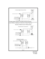
Page 17: ...tos conmutados de bloqueo de puerta En esta aplicación se utilizará un relé para invertir la señal de salida de bloqueo de puerta del módulo Conecte los alambre azul y verde como se muestra a continuación Circuitos de bloqueo de puerta de tipo positivo ...

Page 18: ...salida negativa después de inicio El alambre de luz azul traza proporcionará un 1 segundo negativo de 250 mA pulsed salida después de arranca el vehículo bajo control de la unidad de arranque remoto Normalmente este alambre se utilizará para bloquear las puertas del vehículo si las puertas se desbloquea automáticamente cuando el sistema antirrobo de fábrica se desarma Alambre Verde Blanco Salida d...

Page 19: ...ibir entrada El alambre marrón rojo proporciona un apagado instantáneo para el módulo de encendido por control remoto en cualquier momento 12V está presente Si la luz de freno de vehículos hacia los focos de luz de freno envía 12 voltios luego conecte el alambre marrón rojo en el lado de salida del interruptor de freno Esto provocará el arranque remoto apagar si se realiza un intento para manejar ...

Page 20: ...é de automoción Conecte el terminal 85 del relé a un fusible fuente de 12 voltios Conecte los contactos común normalmente abiertos y normalmente cerrados del relé para realizar la función de canal 3 Alambre Marrón Negro salida de bocina 250 mA El alambre marrón negro viene a pitar la bocina del vehículo Esto es una corriente de salida transistorizada baja y sólo debe conectarse a la salida negativ...

Page 21: ...ón localice y conecte el cable púrpura blanco a la señal de velocidad adecuada y a continuación repita el tach aprender rutina De función seleccionable configuración Función Banco 1 canales de programación de transmisor Empezar con el sistema desarmado gire el interruptor de encendido a la posición de encendido entonces 1 Presione y suelte Interruptor pulsador valet 3 veces Sirena suena una vez y ...

Page 22: ...DEINICIO Para iniciar el temporizador de inicio dentro de 10 segundos después de apagar el interruptor de encendido activar el comando de RF para iniciar 2 veces Pulse el botón de inicio cuatro veces Las luces parpadean y la sirena sonará 2 o 4 veces Esto indica que se ha iniciado el modo de temporizador de intervalo El vehículo Arranque automáticamente cada 2 o 4 horas según lo programado Para ca...

Page 23: ...robado todas las características de seguridad del sistema 1 Monte arriba y detrás del tablero el módulo de control de fijación con tornillos o amarres de alambre Asegúrese de que el elegido en el lugar de montaje no inhibe ninguno de los controles del vehículo 2 Cuidar a Ate los cables hacia arriba y alejados de las piezas móviles y calientes que entre en contacto con debajo del tablero o en las á...

Page 24: ... Este dispositivo debe aceptar cualquier interferencia recibida incluyendo interferencia que pueda causar un funcionamiento no deseado PRECAUCIÓN Los cambios o modificaciones no aprobados expresamente por la parte responsable del cumplimiento anula la autoridad del usuario para operar este aparato Para soporte técnico vaya a www prestigecarsecurity com o llame al 1 800 225 6074 2012 Audiovox Elect...

Reviews: