background image

9

English

CHARGING THE BATTERY
The UPS will charge the internal batteries whenever the UPS is connected to
an AC source and there is an acceptable AC voltage present (90 - 150VAC).  It
is recommended that the UPS's batteries be charged for a minimum of 4 hours
before use.  The UPS may be used immediately, however, the “On Battery”
runtime maybe less than normally expected.  NOTE:  If the UPS is going to be
out of service or stored for a prolonged period of time, the batteries must be
recharged for at least twenty-four hours every ninety days.

USB COMMUNICATIONS PORT CONNECTION (OPTIONAL)
The Power Monitoring Software can be used with the UPS.  Use the interface
cable that comes with the UPS.  Connect one end of the USB cable to the USB
communications port on the rear panel of the UPS.  Connect the other end of
the USB cable to the device that will be monitoring/controlling the UPS.  NOTE:
Connecting to the communications port is optional.  The UPS works properly
without this connection.

CONNECTING THE UPS TO AN AC SOURCE
CAUTION - To reduce the risk of fire, connect only to a circuit provided with 20
amperes maximum branch circuit over-current protection in accordance with
the National Electric Code, ANSI/NFPA 70.  Plug the UPS into a two pole, three
wire, grounded receptacle only.  Do not use extension cords, adapter plugs, or
surge strips.

CONNECTING YOUR EQUIPMENT
Plug the mission critical equipment into the Battery Backup & Surge output
receptacles on the rear panel of the UPS.  Plug the non-critical equipment into
the Surge Only output receptacles on the rear panel of the UPS.  Do not use
extension cords, adapter plugs or surge strips on the output of the UPS.  En-
sure that you do not exceed the maximum output rating of the UPS (refer to the
information label or the electrical specifications in this manual).

CAUTION!  DO NOT connect a laser printer to the output recep-
tacles on the UPS.

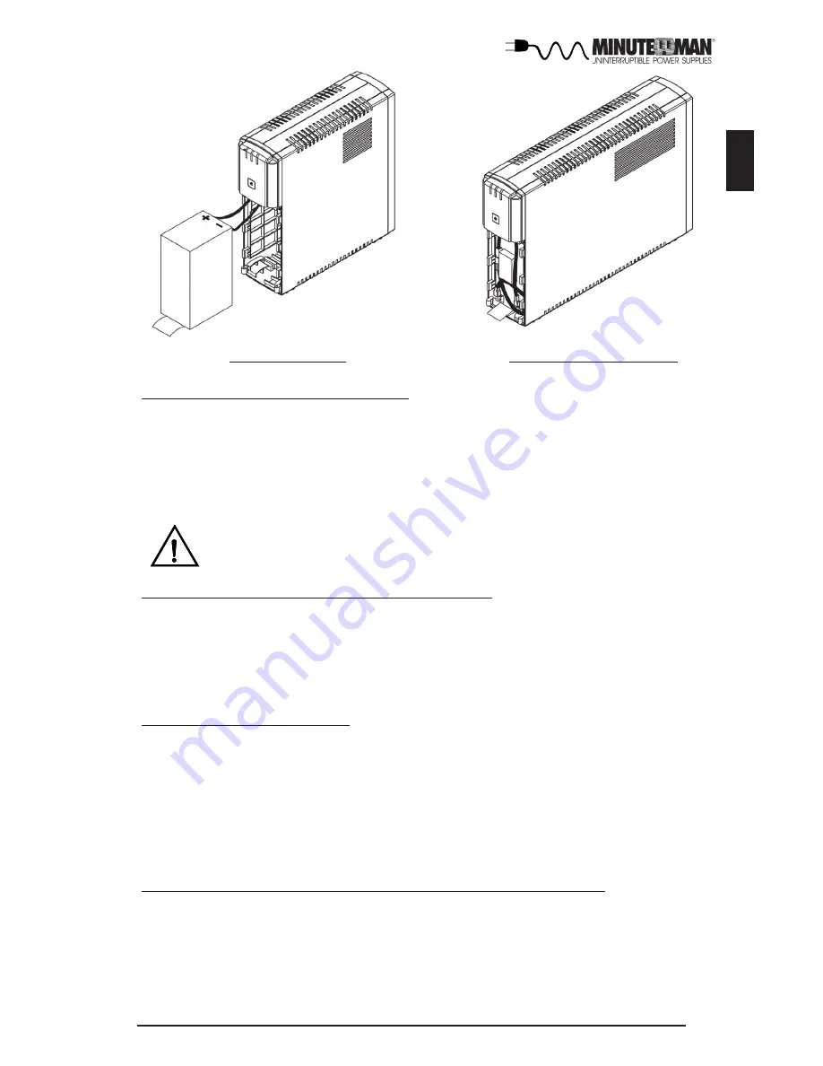
FIG. 3: ETR700

FIG. 3: ETR1000/1500

Summary of Contents for ETR500

Page 1: ...User s Manual Entrust Series UPS...

Page 2: ...tion 2 2 Controls and Indicators 6 3 Installation 7 4 Operation 10 5 Troubleshooting 12 6 Replacing the Battery 13 7 Obtaining Service 16 8 Specifications 17 9 Limited Product Warranty 19 A1 Declarati...

Page 3: ...and main tenance of the UPS and batteries allowing you to correctly set up your system for the maximum safety and performance Included is information on customer support and factory service if it is...

Page 4: ...t breaker or fuse Connection to any other type of receptacle may result in a shock hazard and violate local electrical codes Do not use extension cords adapter plugs or surge strips English CAUTION To...

Page 5: ...imits are designed to provide reasonable protection against such interference in a residential installation This equip ment generates and uses radio frequency and if not installed and used properly th...

Page 6: ...ected under the circumstances Examples of devices considered to be life support devices are neonatal oxygen analyzers nerve stimulators whether used for anesthesia pain relief or other purposes auto t...

Page 7: ...s port is for UPS monitoring and control 8 The RJ11 45 are used for phone fax modem and network protection 9 Battery Backup and Surge output power receptacles 10 Input circuit breaker Output Power Rec...

Page 8: ...he installation procedure These UPSs are shipped with the internal batteries discon nected The batteries must be connected before putting these UPSs into service See the Connecting The Batteries proce...

Page 9: ...y pull tab and gently pull the battery out far enough to connect the battery positive Red wire FIG 3 NOTE The ETR1000 1500 have Red Anderson connectors to connect the battery 5 Verify proper polarity...

Page 10: ...controlling the UPS NOTE Connecting to the communications port is optional The UPS works properly without this connection CONNECTING THE UPS TO AN AC SOURCE CAUTION To reduce the risk of fire connect...

Page 11: ...level the UPS will automatically transfer back to the AC normal mode and start recharging the batteries During an extended outage when there is approximately two minutes of backup time re maining the...

Page 12: ...ER MONITORING SOFTWARE The UPS comes with power monitoring software See the software CD for the installation of the power monitoring software ALARMS ON BATTERY When the UPS is operating on the batteri...

Page 13: ...eries may be weak or at the end of use ful service life Charge the batteries for 8 hours and retest If the runtime is still less than expected the batteries may need to be replaced even though the Wea...

Page 14: ...the supplier Although the battery system voltage is only 12VDC and 24VDC the battery system can still present a risk of electrical shock These batteries produce sufficient current to burn wire or tool...

Page 15: ...gative Black wire FIG 3 NOTE DO NOT short the battery wires together 10 Remove the battery and set aside NOTE Orient the new battery in the same direction as the original battery 11 Place the new batt...

Page 16: ...15 English FIG 1 FIG 2 FIG 3 ETR500 FIG 3 ETR700 FIG 3 ETR1000 1500...

Page 17: ...le F A technician will ask you for the above information and if possible help solve your problem over the phone In the event that the unit requires factory service the technician will issue you a Retu...

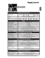
Page 18: ...5 ETR500 Model Number SYSTEM SPECIFICATIONS Voltage Range Topology Line Interactive Simulated Sine Wave OUTPUT NON BATTERYOPERATION INPUT Number of Phase Single 1 2W G Nominal Voltage 120VAC Low Volta...

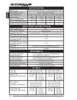
Page 19: ...mode EMI RFI suppression 45 dBA 1 5 6500 Amps total PHYSICAL Weight Net ETR700p15 ETR1500p15 Size Net L X W X H Size Shipping L X W X H ETR700p15 ETR1500p15 Weight Shipping ETR700p15 ETR1500p15 13 23...

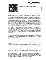
Page 20: ...en used in a manner contrary to the product s User s Manual or other written instructions Any technical advice furnished before or after delivery in regard to use or application of Para Systems s equi...

Page 21: ...ive Carrollton Texas 75007 USA Type of Equipment Uninterruptible Power Supplies UPS Model No ETR500 ETR700 ETR1000 ETR1500 ETR700p15 ETR1500p15 I hereby declare that the equipment specified above conf...

Page 22: ...21 English Notes...

Page 23: ...22 English Notes...

Page 24: ......

Page 25: ...Para Systems Inc 1455 Lemay Dr Carrollton TX 75007 Phone 1 972 446 7363 Fax 1 972 446 9011 Internet minutemanups com UPS Sizing sizemyups com PN 34000295 R1...

Reviews: