background image

25

24

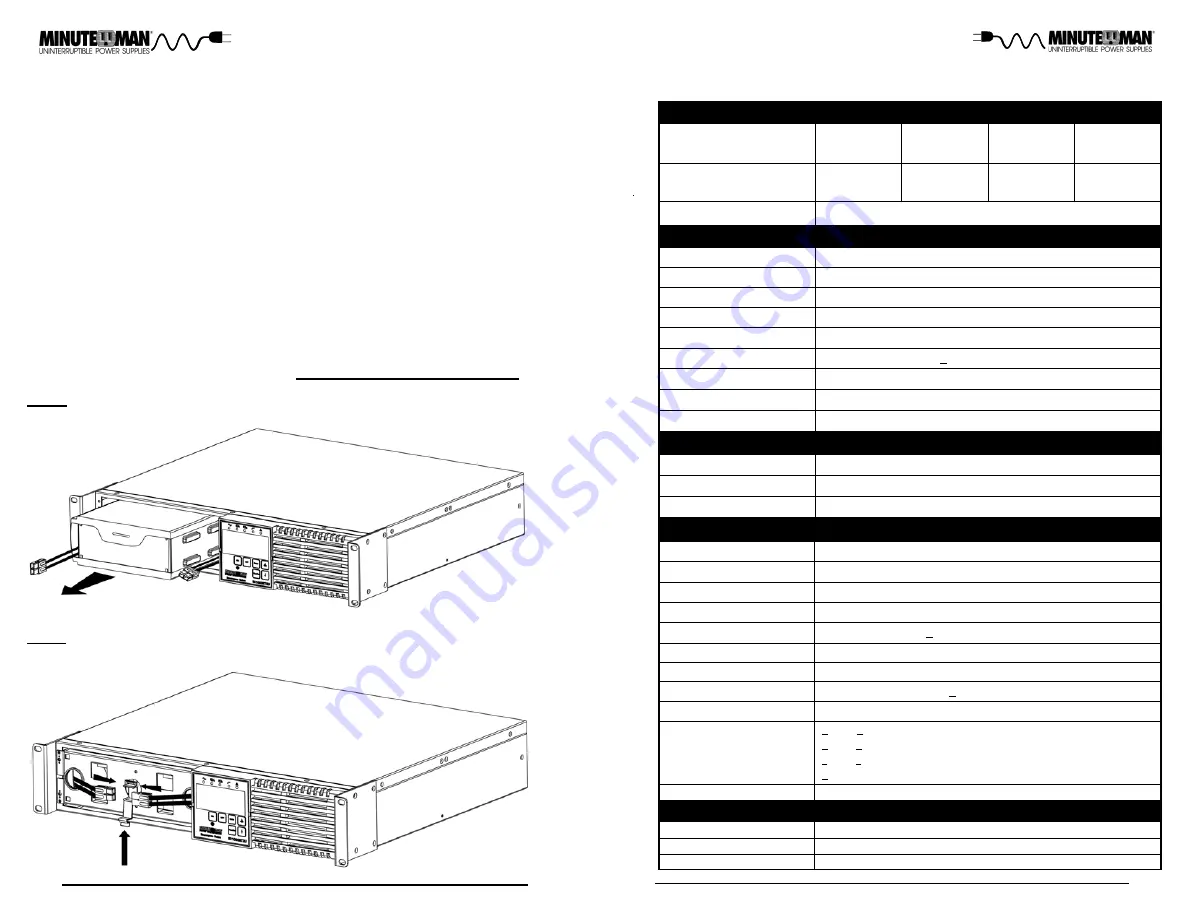
10.Grasp the battery pull tab and gently pull the battery module out of the UPS

and set it aside. (FIG. 3)

NOTE:

Use Caution, the battery module is heavy.

11. Slide the new battery module into the UPS.
12.Re-install the battery retaining bracket.
13.Re-install the two retaining screws for the battery retaining bracket.
14.Verify proper polarity.  Reconnect the battery connectors (red and black).
(FIG. 4)

NOTE:

Some sparking may occur this is normal.

15.Place the battery connectors in the holder and then lock in place. (FIG. 4)
16.Re-install the battery door on the UPS.
17.The UPS is now ready for the normal operation.
18.Properly dispose of the old battery module at an appropriate recycling fac-

ility or return them to the supplier in the packing material that the new batt-
ery module came in.

NOTE:

 If the UPS has a Weak/Bad Battery Alarm after replacing the battery

module, the user must initiate a battery test to clear the Weak/Bad Battery
Alarm.  To initiate a self test see section 4 "

USER INVOKED BATTERY TEST

".

FIG. 3

FIG. 4

120VAC (110, 127VAC)

1500VA

1350W

1000VA

900W

Protection

Waveform Type

Over-Current, Short-Circuit Protected and Latching Shutdown

True Sine Wave

Frequency

50/60Hz, +/-0.2Hz (unless synchronized to utility)

Nominal Voltage (Adjustable)

Maximum Power Capacity

0 ms Typical

>90% (Full Load)

Resettable Circuit Breaker

50 or 60 Hz, +/-6Hz, autosensing

0 - 160VAC

55V (load dependent)  - 150VAC

N/-2%

Transfer Time

Efficiency (Line Mode)

Input Protection

Frequency Limits

Voltage Regulation

Acceptable Input voltage

EC1000RT2U

EC1500RT2U

Model Number

SYSTEM SPECIFICATIONS

Voltage Range

Topology

Double Conversion On-Line, True Sine Wave

OUTPUT NON-BATTERY OPERATION

INPUT

Number of Phase

Single (1


2W +G)

Nominal Voltage

120VAC

Low Voltage Transfer Point

55V (load dependent) resets to Utility Power at 75V or higher

High Voltage Transfer Point

150V resets to Utility Power at 145V or lower

Frequency Range

60Hz: 54 - 66Hz or 50Hz: 44 - 56Hz

OUTPUT BATTERY OPERATION

Voltage Regulation

N/-2% (until Low Battery Warning)

Voltage T.H.D.

<3% (Full Linear Load)

+/-5% @ 100% Load change in 30 ms

Dynamic Response

Slew Rate

<1Hz / second

Overload Capacity

>106 to <110% for 2-mins; AC mode: Transfer to Bypass, DC Mode: Shutdown

>111 to <125% for 1-min; AC mode: Transfer to Bypass, DC Mode: Shutdown

>126 to <150% for 30-secs; AC mode: Transfer to Bypass, DC Mode: Shutdown

>151% Immediately; AC mode: Transfer to Bypass, DC Mode: Shutdown

EC2000RT2U

EC3000RT2U

2000VA

1800W

3000VA

2700W

Chapter 9:  Specifications

Switches from Bypass to Inverter

+/-10% Of the rated input voltage

Switches from Inverter to Bypass

ECONOMY MODE OPERATION

Transfer Time

8 ms Typical

Resets 5VAC from Switch Point

Power Factor Correction

>99% at Full Load

Crest Factor

3 : 1

Summary of Contents for Minuteman Encompass EC1000RT2U

Page 1: ...ser s Manual Encompass RT On Line UPS Series Para Systems Inc 1455 Lemay Dr Carrollton TX 75007 Phone 1 972 446 7363 Fax 1 972 446 9011 Internet minutemanups com UPS Sizing sizemyups com PN 34000519 R...

Page 2: ...6 3 Installation 9 4 Operation 14 5 Configurable Parameters Settings 19 6 Obtaining Service 20 7 Troubleshooting 21 8 Replacing the Battery 22 9 Specifications 25 10 Limited Product Warranty 27 A1 De...

Page 3: ...Hazardous live parts inside these power supplies are energized from the battery even when the AC input is disconnected CAUTION To reduce the risk of electrical shock in conditions where the load equi...

Page 4: ...AC wall outlet 3 To de energize the UPS completely disconnect the battery Life Support Policy As a general policy we do not recommend the use of any of our products in life support applications where...

Page 5: ...od 8 The LCD displays the status of the UPS 9 Pressing the Enter button saves the changes made to the UPS settings 10 Pressing the Page Up button goes to the previous page or will change the UPS setti...

Page 6: ...utility power 6 The option slot is for option cords 7 The Battery Backup output receptacles The output receptacles are electrically wired into two segments to support the Load Shedding Function Labele...

Page 7: ...ation is complete See Connecting your Equipm ent CONNECTING THE BATTERIES QUALIFIED SERVICE PERSONNELONLY Please read all of the WARNINGS and CAUTIONS before attempting to con nect the batteries WARNI...

Page 8: ...r hours every ninety days CHECKING THE SITE WIRING FAULT After plugging the UPS into the AC wall outlet check the Site Wiring Fault icon on the front panel of the UPS If the Site Wiring Fault icon is...

Page 9: ...ge condition occurs the UPS will transfer to the battery mode the inverter will turn on powering the connected equipment the On Battery indicator will illuminate and the audible alarm will sound once...

Page 10: ...re Once the Economy mode has been Enabled the LCD will display ECO and the Bypass Yellow LED will be illuminate Turn on the connected equipment one at a time OPTION SLOT The option slot on the rear pa...

Page 11: ...When the UPS detects a hardware and or internal fault the Fault icon will illuminate and the audible alarm will beep continuously The fault condition in some instances may be reset by turning the UPS...

Page 12: ...the UPS press the On but ton If UPS works normally the software has control of the UPS Charge the batteries for 8 hours and retest If the runtime is still less than expected the batteries may need to...

Page 13: ...to the skin and eyes and may be toxic QUALIFIED SERVICE PERSONNEL ONLY CAUTION Do not dispose of batteries in a fire The batteries may explode The batteries in this UPS are recyclable Dispose of the...

Page 14: ...aximum Power Capacity 0 ms Typical 90 Full Load Resettable Circuit Breaker 50 or 60 Hz 6Hz autosensing 0 160VAC 55V load dependent 150VAC Nominal 2 Transfer Time Efficiency Line Mode Input Protection...

Page 15: ...t parts and warranty labor will be borne by Para Systems For equipment located outside of the United States and Canada Para Systems only covers faulty parts Para Systems products that are depot repair...

Page 16: ...C1000RT2U Y EC1500RT2U Y EC2000RT2U Y EC3000RT2U Y I hereby declare that the equipment specified above conforms to the above Directive s Place Carrollton Texas USA Date July 10 2017 Robert Calhoun Nam...

Reviews: