background image

MMR2 Installation and Service Manual


Ver 1

1

Intended Audience

This manual is for technicians trained to install and service Parabit Systems, Inc.

 MMR2 card readers.

Trademark Acknowledgments

ACS-1EUL, ACS Enterprise, AFH Service, AVA, AXSView Service, MMR2, and SkimGard are registered 

trademarks of Parabit Systems Inc. or its subsidiaries in the United States and/or other countries.
Parabit Systems, Inc. and Parabit are trademarks of Parabit Systems Inc. or its subsidiaries in the United 

States and/or other countries.
All other trademarks and trade names are the property of their respective owners.

FCC Compliance Statement (United States)

This device complies with Part 15 of the Federal Communications Commission (FCC) Rules.  Operation 

is subject to the following two conditions:
This device may not cause harmful interference.
This device must accept any interference received, including interference that may cause undesired 

operation.

CAUTION:

Changes or modifications to this unit not expressly approved by the party responsible for compliance 

could void the user's authority to operate this equipment.
This equipment has been tested and found to comply with the limits for a Class B digital device, pursu

-

ant to Part 15 of the FCC Rules. These limits are designed to provide reasonable protection against 

harmful interference in a residential installation. This equipment generates, uses, and can radiate radio 

frequency energy and, if not installed and used in accordance with the manufacturer's instructions, 

may cause interference harmful to radio communications.
There is no guarantee, however, that interference will not occur in a particular installation. If this equip

-

ment does cause harmful interference to radio or television reception, which can be determined by 

turning the equipment off and on, the user is encouraged to try to correct the interference by one or 

more of the following measures:
Reorient or relocate the receiving antenna.
Increase the separation between the equipment and receiver.
Connect the equipment to an outlet on a circuit different from that to which the receiver is con

-

nected.
Consult the dealer or an experienced radio or TV technician for help


The FCC identifier for this device is FCC ID:2AUGM-MMR2. 
This device contains FCC Certified RF module with FCC ID: 2AA9B05. 
Co-location of this module with other transmitters that operate simultaneously has been evaluated 
using the FCC multi-transmitter procedures. 

.

Preface

Summary of Contents for MMR2

Page 1: ...Parabit Systems Inc MMR2 Installation and Service Manual Release Version 1 3 Parabit Systems Inc 35 Debevoise Avenue Roosevelt NY 11575 October 2019...

Page 2: ...E Copyright 2019 by Parabit Systems Inc All rights reserved No part of the contents of this book may be reproduced or transmitted in any form or by any means without the written permission of the publ...

Page 3: ...lation 5 Overview 5 MMR2 Install Diagrams 5 Electrical Installation 8 MMR2 Wiring 8 Wiring the Card Readers and Basic Input Devices 8 ACS 1EUL Card Reader and Input Device Wiring 10 Chapter 2 Post Ins...

Page 4: ...Table of Contents ii This page intentionally left blank...

Page 5: ...tested and found to comply with the limits for a Class B digital device pursu ant to Part 15 of the FCC Rules These limits are designed to provide reasonable protection against harmful interference i...

Page 6: ...information Convention Example Screen names dialog box names tab names window names field names and menu names appear in bold font Click the Customer box File names are italicized AxsView Transceiver...

Page 7: ...eader To return to your previous location in the manual after following a hyperlink press Alt Left Arrow To return to the hyperlink destination after returning to the previous location press Alt Right...

Page 8: ...Preface 4 MMR2 Installation and Service Manual Ver 1 This page intentionally left blank...

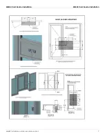
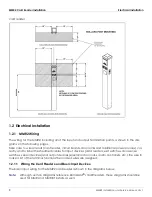
Page 9: ...Installation 5 1 2 Electrical Installation 8 1 1 MMR2 Card Reader Installation 1 1 1 Overview The MMR2 uses Near Field Communication NFC to read contactless EMV cards and mobile devices as well as ma...

Page 10: ...r Installation MMR2 Card Reader Installation 6 MMR2 Installation and Service Manual Ver 1 Note Although the diagrams reference SkimGard IMSR readers these diagrams should be used for MMR and MMR BT in...

Page 11: ...MMR2 Card Reader Installation MMR2 Card Reader Installation MMR2 Installation and Service Manual Ver 1 7...

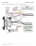
Page 12: ...dditional power sources cor rectly and to label the sheathed cables for input devices card readers exit switches door sense switches sensor devices and output devices electrical door locks alarm contr...

Page 13: ...Electrical Installation MMR2 Card Reader Installation MMR2 Installation and Service Manual Ver 1 9 Note The wiring diagram below applies to both the ACS 1E and ACS 1EUL...

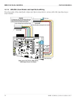
Page 14: ...Electrical Installation 10 MMR2 Installation and Service Manual Ver 1 1 2 1 2 ACS 1EUL Card Reader and Input Device Wiring The other ends of the sheathed cables and their connection to various ACS 1EU...

Page 15: ...Electrical Installation MMR2 Card Reader Installation MMR2 Installation and Service Manual Ver 1 11 The wiring configuration for the Second card reader board is similar to that of the Controller...

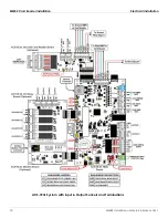
Page 16: ...MMR2 Card Reader Installation Electrical Installation 12 MMR2 Installation and Service Manual Ver 1 ACS 1EUL System with Input Output Sockets and Terminations...

Page 17: ...in the table below TABLE 2 1 Controller Default Settings Function Description Default Settings BIN Files NYCE list of acceptable magnetic card numbers Inserted in ACS 1E memory for both card reader fi...

Page 18: ...osed NC with jumper across the terminal block when Exit switch is not required Egress Activation Time Delay time for an active door control relay after an Egress switch is activated 5 seconds Door Ove...

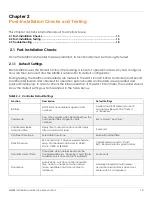
Page 19: ...ight indicator Amber Light Insert Card Green Light Door Unlocked Red Light Door Locked b Screws Parabit provided security torque screws must be used Note NEVER use power tools to tighten Card Reader s...

Page 20: ...Post Installation Checks and Testing Post Installation Testing 16 MMR2 Installation and Service Manual Ver 1 2 2 1 Main Card Reader Tests...

Page 21: ...martphone with a digital wallet installed containing one active credit card When planning to perform an MMR2 skim test a device that operates as an NFC reader is required Begin by turning on the ACS 1...

Page 22: ...ck out mode will not accept any cards Solid amber card accept mode see below Green on schedule open If the reader is amber and not reading cards remove and wire the reader directly to the con troller...

Reviews: