background image

Summary of Contents for 835102

Page 1: ...Serious Steel 835102 HIP SLED ASSEMBLY INSTRUCTIONS I I I Part 6754601 1 Revision 5 24 00...

Page 2: ...ment Tominimize risk please followthese rules 1 Inspect equipment daily Tightenall loose connectionsand replace wornparts immediately Failure to doso may result in serious injury 2 Donot allow minorso...

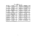
Page 3: ...R BUM ER PARTSLIST 1 25 1 26 2 27 1 28 1 29 1 30 2 31 1 32 1 33 1 34 1 35 1 36 1 37 2 38 1 39 1 40 2 41 1 42 1 43 4 44 4 45 2 46 2 47 2 PART DES CRIPTION 6270501 4 X 14 NON SKID STRIP 6405201 6416601...

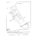
Page 4: ...emble the PEAK UPP _IGHT 6 to the BASE 1 as shownin FIGURE 1 using two 1 2 X 3 1 4 BOLTS 41 1 2 WASHERS 32 and two 1 2 LOCK NUTS 33 SECURELY assemble the P _IGHT 4 and LEFTHANDLES 5 to the BASE 1 on t...

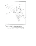
Page 5: ...n in FIGURE Assemble the PLATFORM 11 between the BUSHINGS on the BASE 1 as shownin FIGURE 2 using two 1 2 X 5 BOLT 3 T andtwo 1 2 LOCKNUS 33 TIGHTEN THE CONNECTIONENOUGHTO REMOVETHE PLAY YET ALLOWING...

Page 6: ...the 1 2 DIA SPRING PIN 47 on the PLATFORM SLEEVE 2 and insert the PLATFORM ADJUSTMENT 12 it Slide the PLATFORM ADJUSTMENT 12 down to the first adjustmenthole andrelease the SPRING PIN 47 Assemblethe P...

Page 7: ...the LEFT 8 and RIGHT RAILS 9 along with the SEAT PAD 18 to the BASE 1 as shownin using two 3 8 X 4 1 2 BOLTS 38 two 3 8 LOCK WASteRS 30 and two 3 8 WASHERS 29 Temporarilyasselnble RAILS to the REAR U...

Page 8: ...shownin FIGURE SECURELY assemble four 3 DIA WHEELS 20 to the sides of the CARRIAGE 16 as shown in FIGURE 6 using 4 1 2 BOLTS 43 eight 1 2 WASHERS 32 and four 1 2 LOW HEIGHT LOCK NUTS 34 Attach one 4 X...

Page 9: ...ETS 14 to the right side of the CARRIAGE 16 as shownin FIGURE 7 using two X 2 3 4 BOLTS 40 two 1 2 WASHERS 32 and two 1 2 LOW I I IGHTLOCK NUTS 34 NOTE TIGHTEN BIIACK ETS SECURELY TO THE CARRIAGE THEN...

Page 10: ...ary 1 2 X4 1 2 BOLTS 43 fromSTEP Swingthe LEFT 8 and RIGHT 9 RAILS out enoughto insert the CARRIAGE ASSEIV LY 16 in between CARRIAGE 16 to rest on the SAFETY STOPS underneaththe RAILS See FIGURE 1 2 1...

Page 11: ...S IN AS FARAS POSSIBLE SECURELY tightenthe two 3 8 X 4 1 2 BOLTS 38 holding the SEATPAD 18 from STEP5 IMPORTANT BEFORE TIGHTENINGMOVE THERAILS IN AS FARAS POSSIBLE To adjust the side to side movement...

Page 12: ...0 SECURELY assemble the WEIGHT SUPPORT 13 to the CARRIAGE 16 as shown in FIGURE 10 using two 1 2 X 4 1 2 BOLTS 43 two 1 2 X 3 1 4 BOLTS 41 eight 1 2 WASHERS 32 and four 1 2 LOCK NUTS 1 2 I 1 2 1 2 1 2...

Page 13: ...emble the two PAD SUPPORTS 3 to the CARRIAGE 16 as shown in FIGURE 11 using two 1 2 X 3 1 4 BOLTS 41 four 1 2 WASHERS 32 and two 1 2 LOCKNUTS 33 SECURELY assemble two SHOULDER PADS 17 to the PADSUPPOR...

Page 14: ...LL_ _LLLLL_ _LLLLL_ _LLL _LLL _L L_ LLL LLLL LLLL LLLL LLLL LLLL LLLL LLLL LLLL LLLL LLLL LLLL LL L STEP 12 Attach two 1 1 4 SQRUBBER BUM ERS 24 to the ends of the ANGLES of the FOOT PLATE 10 as shown...

Page 15: ...13 Assemble the FOOT PLATE 10 to the CAR AGE 16 as shown in FIGURE 13 using two 1 2 X 1 1 4 BOLTS 39 two WASHERS 32 and two 1 2 LOWHEIGHTLOCKNUTS 34 TIGHTENTI IE CONNECTION COMPLETELY BACKTI IE NUTSOF...

Page 16: ...s far as possible then lower the BAR 7 into the SURE LOC BUSHING at the bottom ol the RAIL MAKE SURE THESTOPPEGSARE VERTICAL then insert one 1 1 4 ROLL PIN 45 into the hole at the tc p the BAR 7 DO NO...

Page 17: ...GURE 15 STEP15 SECURELY assemble the PAD STOP 15 to the BACK PAD 19 as shownin FIGURE 15 using t vo 3 8 X 1 BOLTS 35 3 8 LOCK WASHERS 30 and two 3 8 WASHERS 29 MAKESURE ALL CONNECTIONS ARE SECURELYTIG...

Page 18: ...S 7 from either the LEGPRESSor HACK SQUAT position begin by moving the CARPJAGE 16 up Grasp the HANDLES or BA the CARRIAGE STOP BA S 7 and push or pull up and rotate them out Now the stops are out of...

Page 19: ...movethe CARRIAGE 16 to the top carriage stop of the CARRIAGE STOP BAR 7 Place feet the HORIZONTAL TUBEofthe CARRIAGE 16 WHERE THENON SKIDSTRIP IS LOCATED DO NOTROTATE THE CARRIAGESTOP BARS DOWN FOR T...

Reviews: