background image

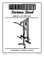
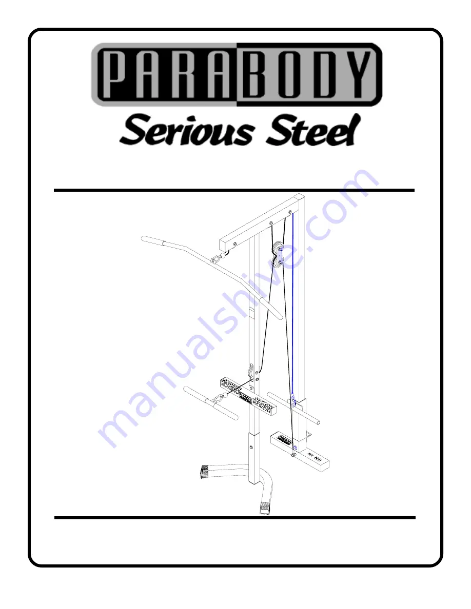
848101 LAT OPTION

Part  #  6826701

Revision:  5/26/99

1

ASSEMBLY INSTRUCTIONS

Summary of Contents for 848101

Page 1: ...848101 LAT OPTION Part 6826701 Revision 5 26 99 1 ASSEMBLY INSTRUCTIONS...

Page 2: ...rchased from your Parabody customer service representative at 800 328 9714 Bolt Length Ruler 0 1 2 3 4 5 6 1 2 1 2 1 2 1 2 1 2 1 2 WELCOMETOTHEWORLDOF Serious steel There is a risk assumed by individu...

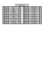
Page 3: ...6480301 6127701 DESCRIPTION 1 1 4 RUBBERBUMPER 1X1 GLIDE 3 8 WASHER 3 8 LOCKNUT 1 2 WASHER 1 2 LOCKNUT 3 8X2 BOLT 3 8X2 1 2 BOLT 3 8X2 3 4 BOLT 3 8X4 1 2 BOLT 1 2X3 BOLT 5 16 SNAPLINK 1 4 QUICKDISCONN...

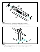
Page 4: ...GURE 1 0 1 2 3 4 5 6 1 2 1 2 1 2 1 2 1 2 1 2 Assemble two 2 SQ COVER CAPS 14 onto the ends of the STAND 3 as shown in FIGURE 1 Insert two 3 X 2 END CAP 15 into the ends of the BASE 1 as shown in FIGUR...

Page 5: ...1 4 SQ RUBBER BUMPER 17 to the CARRIAGE 5 as shown in FIGURE 4 Insert two 2 SQ END CAPS 13 into the ends of the CROSS BRACE 4 as shown in FIGURE 3 16 12 4 18 5 17 13 Attach eight 1 X 1 GLIDES 18 to th...

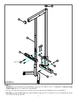
Page 6: ...2 3 4 5 6 1 2 1 2 1 2 1 2 1 2 1 2 Slide the CARRIAGE 5 over the UPRIGHT 2 as shown in FIGURE 5 Assemble the STAND 3 to the UPRIGHT 2 as shown in FIGURE 5 1 3 5 2 Assemble the BASE 1 to the UPRIGHT 2...

Page 7: ...SIDEoftube andone1 2 LOCKNUT 22 SeeFIGURE6 Insert one 3 X 2 END CAP 15 and one 2 SQ END CAP 13 into the ends of the UPRIGHT 2 as shown in FIGURE 6 SECURELYassembletheCROSSBRACE 4 totheUPRIGHT 2 usingt...

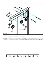
Page 8: ...he UPRIGHT 2 as shown in FIGURE 7 SECURELYassemblethree3 1 2 PULLEYS 11 intotheslotsoftheUPRIGHT 2 usingthree3 8X2 3 4 BOLTS 25 six3 8 FLANGE SPACERS 31 and three 3 8 LOCK NUTS 20 as shown in FIGURE 7...

Page 9: ...2 as shown in FIGURE8 LOOSELY assemble two 3 16 X 1 3 4 X 5 1 4 PLATES 8 to each side of the 3 1 2 PULLEY 11 using one 3 8 X 2 BOLT 23 two 3 8 WASHERS 19 and one 3 8 LOCK NUT 20 See FIGURE 8 Attach t...

Page 10: ...8 LOCKNUTS 20 NOTE TheCABLE 9 shouldberoutedbetweenthepulleyandtheretainingboltasshowninFIGURE9 Loop the CABLE 9 around one 3 1 2 PULLEY 11 as shown in FIGURE 9 LOOSELYassemblethe3 1 2 PULLEY 11 toth...

Page 11: ...11 STEP 10 FIGURE 10 SECURELYassemble the CABLE 9 to the BASE 1 using one 3 8 X 4 1 2 BOLT 26 one 3 8 X 1 SPACER 32 and one 3 8 LOCK NUT 20 as shown in FIGURE 10 9 26 3 8 X 4 1 2 1 32 20...

Page 12: ...28 as shown in FIGURE 11 Attach the LOW ROW BAR 7 to the ball end of the lower CABLE 9 using one 5 16 SNAP HOOK 28 as shown in FIGURE 11 Slide two 1 X 8 GRIPS 10 on the LOW ROW BAR 7 and two 1 X 8 GRI...

Page 13: ...lt the 848101 back and remove the STAND 3 as shown in FIGURE 12 To use the 848101 LATOPTION NOTE LATOPTION MUSTBE USEDWITHABENCH LATOPTION CANNOTBE USED WHILESTANDISATTACHED STANDMUSTBEATTACHEDWITHTHE...

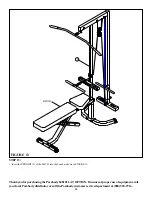
Page 14: ...OPTION If unsure of proper use of equipment call your local Parabody distributor or call the Parabody customer service department at 800 328 9714 BENCH 2 STEP 13 FIGURE 13 Insert the UPRIGHT 2 of the...

Reviews: