background image

Please note:

Tools Required for Assembly

* Thank you for purchasing the Parabody 848101 LAT OPTION. Please read these instructions

thoroughly and keep them for future reference. This product must be assembled on a flat, level
surface to assure its proper function.

* 3/4” wrench
* 9/16” wrench
* Ratchet with 3/4” and 9/16” sockets
* Adjustable wrench
* Tape measure

2

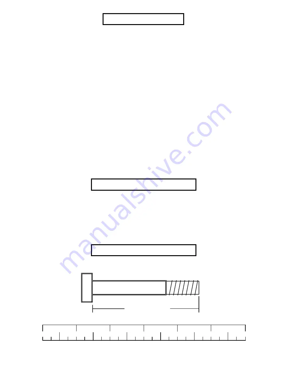
NOTE: BOLT LENGTH IS MEASURED FROM THE UNDERSIDE OF THE HEAD OF THE BOLT.

   BOLT LENGTH RULER:

  We recommend cleaning your product (pads and frame) on a regular basis, using warm soapy
   water. Touch-up paint can be purchased from your Parabody customer service representative
   at (800) 328-9714.

Bolt Length Ruler

0

1

2

3

4

5

6

1/2

1/2

1/2

1/2

1/2

1/2

WELCOME TO THE WORLD OF


S

erious

 s

teel!

There is a risk assumed by individuals who use this type of equipment. To minimize risk, please
follow these rules:

2. Do not allow minors or children to play on or around this equipment.

1. Inspect equipment daily. Tighten all loose connections and replace worn parts immediately.
    Failure to do so may result in serious injury.

3. Exercise with care to avoid injury.

4. If unsure of proper use of equipment, call your local Parabody distributor or call the
    Parabody customer service department at (800) 328-9714.

BOLT LENGTH

5. Consult a physician before beginning any exercise program.

IMPORTANT NOTES

Summary of Contents for 848101

Page 1: ...848101 LAT OPTION Part 6826701 Revision 5 26 99 1 ASSEMBLY INSTRUCTIONS...

Page 2: ...rchased from your Parabody customer service representative at 800 328 9714 Bolt Length Ruler 0 1 2 3 4 5 6 1 2 1 2 1 2 1 2 1 2 1 2 WELCOMETOTHEWORLDOF Serious steel There is a risk assumed by individu...

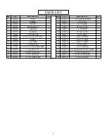
Page 3: ...6480301 6127701 DESCRIPTION 1 1 4 RUBBERBUMPER 1X1 GLIDE 3 8 WASHER 3 8 LOCKNUT 1 2 WASHER 1 2 LOCKNUT 3 8X2 BOLT 3 8X2 1 2 BOLT 3 8X2 3 4 BOLT 3 8X4 1 2 BOLT 1 2X3 BOLT 5 16 SNAPLINK 1 4 QUICKDISCONN...

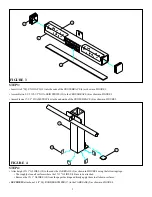
Page 4: ...GURE 1 0 1 2 3 4 5 6 1 2 1 2 1 2 1 2 1 2 1 2 Assemble two 2 SQ COVER CAPS 14 onto the ends of the STAND 3 as shown in FIGURE 1 Insert two 3 X 2 END CAP 15 into the ends of the BASE 1 as shown in FIGUR...

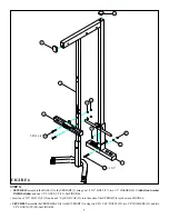
Page 5: ...1 4 SQ RUBBER BUMPER 17 to the CARRIAGE 5 as shown in FIGURE 4 Insert two 2 SQ END CAPS 13 into the ends of the CROSS BRACE 4 as shown in FIGURE 3 16 12 4 18 5 17 13 Attach eight 1 X 1 GLIDES 18 to th...

Page 6: ...2 3 4 5 6 1 2 1 2 1 2 1 2 1 2 1 2 Slide the CARRIAGE 5 over the UPRIGHT 2 as shown in FIGURE 5 Assemble the STAND 3 to the UPRIGHT 2 as shown in FIGURE 5 1 3 5 2 Assemble the BASE 1 to the UPRIGHT 2...

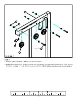
Page 7: ...SIDEoftube andone1 2 LOCKNUT 22 SeeFIGURE6 Insert one 3 X 2 END CAP 15 and one 2 SQ END CAP 13 into the ends of the UPRIGHT 2 as shown in FIGURE 6 SECURELYassembletheCROSSBRACE 4 totheUPRIGHT 2 usingt...

Page 8: ...he UPRIGHT 2 as shown in FIGURE 7 SECURELYassemblethree3 1 2 PULLEYS 11 intotheslotsoftheUPRIGHT 2 usingthree3 8X2 3 4 BOLTS 25 six3 8 FLANGE SPACERS 31 and three 3 8 LOCK NUTS 20 as shown in FIGURE 7...

Page 9: ...2 as shown in FIGURE8 LOOSELY assemble two 3 16 X 1 3 4 X 5 1 4 PLATES 8 to each side of the 3 1 2 PULLEY 11 using one 3 8 X 2 BOLT 23 two 3 8 WASHERS 19 and one 3 8 LOCK NUT 20 See FIGURE 8 Attach t...

Page 10: ...8 LOCKNUTS 20 NOTE TheCABLE 9 shouldberoutedbetweenthepulleyandtheretainingboltasshowninFIGURE9 Loop the CABLE 9 around one 3 1 2 PULLEY 11 as shown in FIGURE 9 LOOSELYassemblethe3 1 2 PULLEY 11 toth...

Page 11: ...11 STEP 10 FIGURE 10 SECURELYassemble the CABLE 9 to the BASE 1 using one 3 8 X 4 1 2 BOLT 26 one 3 8 X 1 SPACER 32 and one 3 8 LOCK NUT 20 as shown in FIGURE 10 9 26 3 8 X 4 1 2 1 32 20...

Page 12: ...28 as shown in FIGURE 11 Attach the LOW ROW BAR 7 to the ball end of the lower CABLE 9 using one 5 16 SNAP HOOK 28 as shown in FIGURE 11 Slide two 1 X 8 GRIPS 10 on the LOW ROW BAR 7 and two 1 X 8 GRI...

Page 13: ...lt the 848101 back and remove the STAND 3 as shown in FIGURE 12 To use the 848101 LATOPTION NOTE LATOPTION MUSTBE USEDWITHABENCH LATOPTION CANNOTBE USED WHILESTANDISATTACHED STANDMUSTBEATTACHEDWITHTHE...

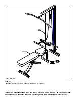
Page 14: ...OPTION If unsure of proper use of equipment call your local Parabody distributor or call the Parabody customer service department at 800 328 9714 BENCH 2 STEP 13 FIGURE 13 Insert the UPRIGHT 2 of the...

Reviews: