background image

893104 PRO SYSTEM

Part  #  6817401

Revision:6/8/99

1

ASSEMBLY INSTRUCTIONS

Summary of Contents for 893104

Page 1: ...893104 PRO SYSTEM Part 6817401 Revision 6 8 99 1 ASSEMBLY INSTRUCTIONS...

Page 2: ...nt can be purchased from your Parabody customer service representative at 800 328 9714 Bolt Length Ruler 0 1 2 3 4 5 6 1 2 1 2 1 2 1 2 1 2 1 2 WELCOMETOTHEWORLDOF S e r i o u ss t e e l There is a ris...

Page 3: ...BOLT 1 2X3 1 4 BOLT 1 2X4 BOLT 1 2X5 1 2 BOLT 3 8 FLANGESPACER 3 8 WASHER 3 8 LOWHEIGHTLOCKNUT 3 8 LOCKNUT 1 2 WASHER 1 2 LOCKNUT 1 2 SPRINGPINASSEMBLY 3 4 STARLOCKCOLLAR 5 16 SNAPHOOK 1 4 QUICKLINK 1...

Page 4: ...rt four 2 SQ END CAPS 22 two 3 X 2 END CAPS 19 to the ends of the FRONT UPRIGHTS 5 as shown in FIGURE 3 0 1 2 3 4 5 6 1 2 1 2 1 2 1 2 1 2 1 2 44 43 19 5 4 1 2 X 4 37 22 FIGURE 2 STEP 2 Attach two NON...

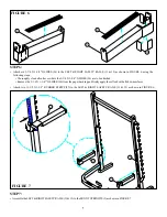
Page 5: ...usingtwo1 2 X3 1 4 BOLTS 36 and two 1 2 LOCK NUTS 44 as shown in FIGURE 4 FIGURE 4 STEP 4 44 2 4 1 2 X 3 1 4 36 22 13 5 Slide the CARRIAGE 13 over the UPRIGHT FRAME 2 as shown in FIGURE 4 Insert one...

Page 6: ...the FRONTUPRIGHTS 5 as shown in FIGURE 5 using two 1 2 X 3 BOLTS 35 two 1 2 WASHERS 43 and two 1 2 LOCK NUTS 44 35 1 2 X 3 14 43 2 7 5 1 2 X 3 35 43 44 LOOSELY assemble the two SMARTRACKS 14 to the ou...

Page 7: ...1 4 X 1 3 4 GLIDES 26 are to be attached Remove the 3 1 4 X 1 3 4 GLIDES 26 from the paper backing and firmly apply them flush with all shown surfaces 12 26 11 Attach two 13 1 2 X 1 5 8 RUBBER STRIPS...

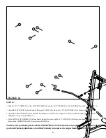
Page 8: ...R SUPPORT 8 to theTOPBOOM 1 using one 3 8 X 2 3 4 32 and one 3 8 LOWHEIGHTLOCK NUT 41 SeeFIGURE9 33 3 8 X 4 32 3 8 X 2 3 4 1 2X2 1 2 34 1 44 43 40 42 19 32 3 8 X 2 3 4 3 8 LOW HEIGHT 41 27 1 8 42 SECU...

Page 9: ...d over bolt SECURELY assemble three 3 1 2 PULLEYS 16 into the slots of the TOP BOOM 1 using three 3 8 X 2 3 4 BOLTS 32 six 3 8 FLANGE SPACERS 39 and three 3 8 LOCK NUTS 42 as shown in FIGURE 10 NOTE M...

Page 10: ...X 5 1 4 PLATES 28 to each side of the 3 1 2 PULLEY 16 using one 3 8 X 2 BOLT 31 two 3 8 WASHERS 40 and one 3 8 LOCK NUT 42 See FIGURE 11 Attach the CABLE 18 from the TOP BOOM 1 to the CARRIAGE 13 usi...

Page 11: ...te the end of the second CABLE 18 through the slot of the UPRIGHT FRAME 2 then SECURELYassemble one 4 1 2 PULLEY 17 to the UPRIGHTFRAME 2 using two 3 8 X 2 3 4 BOLTS 32 two 3 8 FLANGE SPACERS 39 two 3...

Page 12: ...ssemble the KNEE SUPPORT 3 to the UPRIGHT FRAME 2 using one 1 2 X 5 1 2 BOLT 38 and one 1 2 LOCK NUT 44 NOTE Donotovertightenthisconnection theKNEESUPPORTshouldrotatefreely SeeFIGURE15 Assemble two 4...

Page 13: ...6 SNAP HOOK 47 as shown in FIGURE 16 Attach the LOW ROW BAR 10 to the ball end of the lower CABLE 18 using one 12 LINK CHAIN 49 and two 5 16 SNAP HOOKS 47 as shown in FIGURE 16 Slide two 1 X 8 GRIPS 2...

Reviews: