background image

Summary of Contents for Leg Press 100101

Page 1: ...1001 O1 LEGPRESS WARNING Readand follow all directions for each step to insure proper assembly of thi product ASSEMBLY INSTRUCTIONS Part 7037301 Rev A 1 Revision 12 4 00...

Page 2: ...rules 1 Inspect equipment daily Tightenall loose connectionsand replace wornp ts immediately Failure to doso may result in serious injury 2 Donot allowminorsor children to play on or aroundthis equipm...

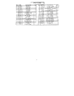
Page 3: ...01 2 WHEEL 3102501 3 8 FLATWASHER PARTSLIST QTY KEY 1 18 1 19 1 20 1 21 2 22 1 23 1 24 2 25 2 26 2 27 1 28 8 29 14 30 1 31 2 32 2 33 8 PART DESCRIP 3N 3102601 3 8 LOCK WASHER 3102802 3102807 3102801 3...

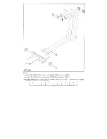
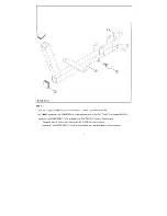
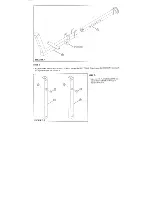
Page 4: ...as shown in FIGURE Insert four 2 SQ ENDCAPS 13 into the ends of the BASE FRAME 1 as shownin FIGURE SECURELY assemble the REAR TUBE 3 to the BASEFRAME 1 using two 3 8 X 3 BOLTS 25 278 FLATWASHE RS 17 a...

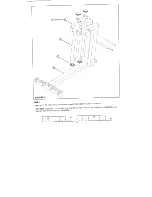
Page 5: ...3 to the spring pin barrel on the SEAT FRAME 2 as shownin FIGURE Attach four PARAGLIDE STRIPS 14 to the inside of the SEAT FRA E 2 using file following steps Thoroughlyclean all surfaces where the PAR...

Page 6: ...one 3 8 X 4 1 2 BOLT 26 as shown in FIGURE Attach four PARAGLIDE STRIPS 14 to the outside of the ADJUSTMENT TUBE 7 using the followirtg steps Thoroughlyclean all surfaces where the PARAGLtDE STRIPS 1...

Page 7: ...ULLE slide the ADJUSTMENT TUBE 7 over into the SEAT FRAME 2 and engage the SPRING PINinto one the adjustmentholes See FIGURE 4 FIGURE5 STEP5 Insert two 3 4 FLANGE BEARINGS into each of the twoLEVER TU...

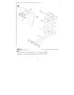
Page 8: ...SQ END CAPS 13 into the ends of twoLEVER TUBES 5 as shownin FIGURE SECURELY assemble the LEVER TUBES 5 to the BASE FRAME 1 using two 3 4 SHAFTS 9 and SECURE in using four 5 16 SETSCREWS 32 See FIGURE...

Page 9: ...FIGURE 7 STEP7 Insert four 2 SQ END CAPS 13 into the endsof FOOT PLATE 4 as shown in FIGURE Insert eight 1 2 FLANGE BEARING 30 into the LEVER TUBES 5 as shown in FIGURE...

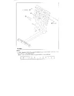
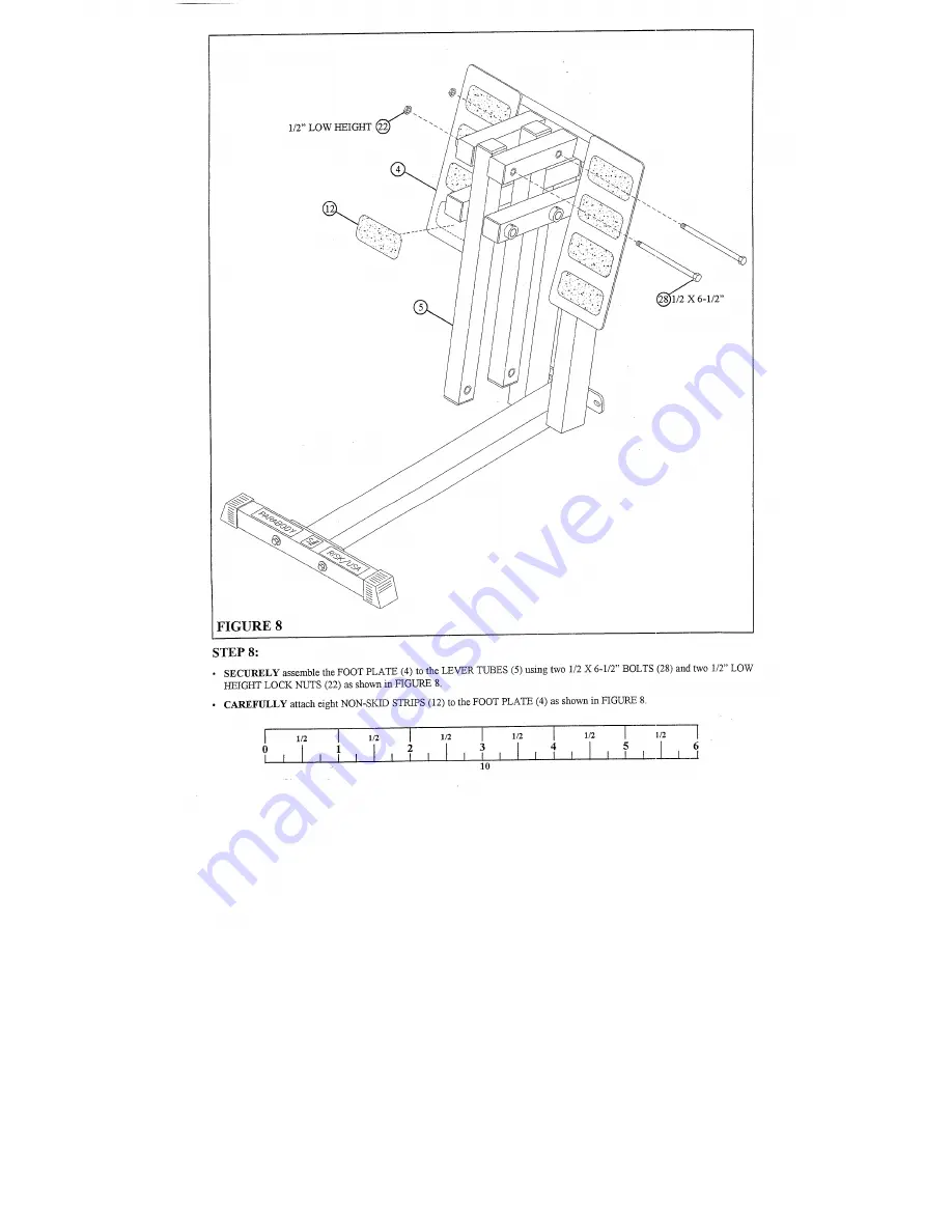
Page 10: ...STEP8 SECURELY assemble the FOOT PLATE 4 to the LEVER TUBES 5 using two 1 2 X 6 1 2 BOLTS 28 and two 1 2 HEIGHT LOCK NUTS 22 as shown in FIGURE CAREFULLY attach eight NON SKID STRIPS 12 to the FOOT PL...

Page 11: ...3 1 4 FIGURE9 STEP9 SECURELY assemble the SEATFRAME 2 to the LEVER TUBES 5 using two 1 2 X 3 1 4 BOLTS 27 and two 1 2 NUTS 21 as shown in FIGURE 11...

Page 12: ...I I I 3 8 X 1 1 2 FIGURE 10 STEP10 SECURELY assemble the SEATPAD 8 to the HANDLE 6 and the SEATFRAME 2 using two 3 8 X 1 1 2 BOLTS two 3 8 LOCK WASHERS 18 and two 3 8 FLATWASHERS 17 See FIGURE 1 2 11...

Page 13: ...FIGURE 11 STEP 11 SECURELY assemble the SEATPAD 8 to the SEATFRAME 2 using two 3 8 X 2 3 4 BOLTS 24 and two 3 8 WASHERS 18 as shown in FIGURE11 Slide two 1 X 8 GRIPS 10 over each HANDLE 6 as shownin F...

Page 14: ...TOR assemblyinstructions to attach the 832102LEG PRESS to the homegym Thank you for purchasing the Parabody 100101 LEGPRESS If unsure of proper use of equipment call your local Parabody distributor or...

Reviews: