background image

Summary of Contents for Serious Steel 877102

Page 1: ...Serious Steel 877102 BODYSMITH NARROW WORKOUT CENTER I ASSEMBLY INSTRUCTIONS Part 6757301 t evlision 1 12 98...

Page 2: ...iniraize risk please follow these rules 1 Inspect equipmem daily Tighten all loose connections and replace wornpa ts immediately Failure to do so mayresult in serious injury 2 Donot allow minors or ch...

Page 3: ...1 21 3102804 22 23 24 25 26 27 28 29 30 31 32 33 3102502 6236701 3102804 6412001 6020601 LEG EXTENSION HINGE TAB U PIN ROLLER PAD SHAFT ROLLER PAD SEAT PAD BAcKPAD 3 8 X 1 BOLT 3 8 X 2 3 4 BoLT 3 8 X...

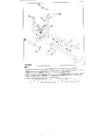
Page 4: ...AGLIDE STRIPSfrom the paper backing and fLrmly apply them to all shownsurfaces Insert one U PIN 10 through the BUSHING of the WOLFF SLEEVE 4 and attach one PALNUT 28 to the end of the 10 as shownin FI...

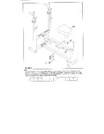
Page 5: ...adjustment holes Insert two 2 SQ END CAPS 33 into both ends of the BASE LEG 5 as shownin FIGURE Insert one U PIN 10 through the BUSHING on the bottom of BENCH FRAME 2 and attach one PALNUT 28 to the...

Page 6: ...3 8 X 3 BOLTS 17 one 3 8 4 BOLT 16 six 3 8 WASHERS 19 and three 3 8 LOCK NUTS 21 as sho vn in FIGURE SECURELY assemble two 3 8 SPRINGPIN ASSEMBLIES 25 to the SPRINGPIN HOUSING on the UPRIGHT FRANIE 1...

Page 7: ...ch SADDLE 6 FOURONEACH END as shown in FIGURE Slide two 1 1 4 X 5 GRIPS 30 over the DIP HANDLES of both SADDLES 6 IF A LUBRICANT IS REQUIRED THE INSIDE OF THE GRIP WITH RUBBINGALCOHOL Pull back the SP...

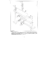
Page 8: ...S 9 over the PIN WOLFF SLEEVE ONEONEACHSIDE as shown in FIGURE5 and SECURELY assemble each HINGETAB 9 to SEATPAD 13 using two 3 8 X 1 BOLTS 15 3 8 LOCK WASHE RS 20 and tw o 3 8 W ASHER S 19 SURE BOTH...

Page 9: ...lide the two remaining HINGE TABS 9 over the PIN WOLFF SLEEVE ONEONEACH SIDE as shown in FIGURE 6 and SECURELY assemble each HINGE TAB 9 to BACK PAD 14 using two 3 g X 1 BOLTS 15 two 3 8 LOCK WASHERS...

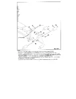
Page 10: ...OLLER PADS 12 over each end of the SHAFT of the LEG EXTENSION NECK 7 as shownin FIGURE 7 secure in place using two 3 4 STARLOCK COLLARS 27 Insert the LEG EXTENSION NECK 7 into the BENCH FRAME 2 and se...

Page 11: ...GEXTENSION NECK 7 as shown in FIGURE 8 using one 1 2 X 3 18 two 1 2 WASHERS 22 and one 1 2 LOW HEIGHTLOCKNUT 24 TIGIITEN TIlE CONNECTION TO REMOVE TIlE PLAY YET ALLOWING TIlE LEG EXTENSION TO ROTATEFR...

Page 12: ...N pull up slowly on the front of the BENCH FRAME 2 a d allow the U PIN 10 to rest ontop of the TABof the BASELEG 5 NOTE THE BENCH FRAME MUST BE ADJUSTED WHENUSING THE LEG EXTENSION TO ALLOW PROPER CLE...

Page 13: ...0 for performing 1NCLL qE or MILITARY PRESSES Whenperforming DIPS use the HEIGHT ADJUSTMENT BAR 3 to hold the BACK PADfonvard as shown in the WORKOUT MANUAL Follow the WORKOUT MANUAL for the correctwa...

Reviews: