background image


203987 Rev A  RCP2-1000 RM Remote Controller Operations Manual 

1.2 Equipment Supplied 

 
The following equipment is supplied with each unit: 
 

• 

RCP2-1000 RM Redundant System Controller (1 RU high) 

• 

(2) IEC Line Cord Sets 

• 

Operations Manual (203987) RCP2-1000 RM System Controller 

 
Paradise Data can provide the following optional equipment: 
 

• 

Rack Slides 

• 

Mating cable for Rack Mount SSPA and RCP2-1000, (Part Number 
L201777). 


1.3 Safety Considerations 

 
Potential safety hazards exist unless proper precautions are observed when working 
with this unit. To ensure safe operation, the user must follow the information, cautions 
and warnings provided in this manual as well as the warning labels placed on the unit 
itself. 
 

1.3.1 High Voltage Hazards 

 
High Voltage for the purpose of this section is any voltage in excess of 30 volts. Volt-
ages above this value can be hazardous and even lethal under certain circumstances. 
Care should be taken when working with devices that operate at high voltage. 
 

• 

All probes and tools that contact the equipment should be properly insulated 
to prevent the operator from coming into contact with the voltage. 

• 

The work area should be secure and free from non-essential items. 

• 

Operators should never work alone on high voltage devices. There should 
always be another person present in the same work area to assist in the 
event of an emergency. 

• 

Operators should be familiar with procedures to employ in the event of an 
emergency, i.e. remove all power, CPR, etc. 

 
An AC powered unit will have 115 VAC or 230 VAC entering through the AC power 
connector. Caution is required when working near this connector, the AC circuit 
breaker, or the internal power supply. 
 

Summary of Contents for RCP2-1000

Page 1: ...2 1000 Remote Controller for Rack Mount SSPAs Paradise Datacom LLC Phone 814 238 3450 328 Innovation Blvd Fax 814 238 3829 State College PA 16803 USA Web www paradisedata com Email sales paradisedata...

Page 2: ...prepared to be used by professional and properly trained personnel and the customer assumes full responsibility when using this document Paradise Datacom welcomes customer comments as part of the proc...

Page 3: ...Cable Connectors 12 2 5 1 Serial Port Main J4 14 2 5 2 Serial Port Local J5 15 2 5 3 Program Port J6 15 2 5 4 Parallel I O Connector J7 15 Section 3 RCP2 1000 RM Front Panel Operation 17 3 0 Introduc...

Page 4: ...ntrol Mode 25 3 2 4 4 Panel ID 25 3 2 5 Options Sub Menu 25 3 2 5 1 Backup User Settings 25 3 2 5 2 Restore 25 3 2 5 3 Lamp Test 25 3 2 5 4 Password 25 3 2 5 5 Reset 25 Section 4 Theory of Operation 2...

Page 5: ...rame Sync Word 34 5 1 1 2 Destination Address 34 5 1 1 3 Source Address 34 5 1 2 Data Packet 35 5 1 2 1 Protocol ID 35 5 1 2 2 Request ID 35 5 1 2 3 Command 35 5 1 2 4 Data Tag 36 5 1 2 5 Error Status...

Page 6: ...Digital Core Board 30 Figure 5 1 Basic Communication Packet 33 Figure 5 2 Header Packet 35 Figure 5 3 Data Packet 35 Figure 5 4 Trailer Packet 38 Figure 6 1 Connection Description Window 40 Figure 6...

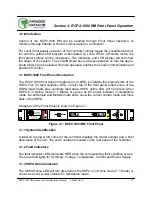
Page 7: ...1000 RM is used for standalone or 1 1 modes of operation An outline drawing of the RCP2 1000 is shown in Figure 1 1 A mimic display on the front panel indicates online and fault status of the equipmen...

Page 8: ...h Voltage for the purpose of this section is any voltage in excess of 30 volts Volt ages above this value can be hazardous and even lethal under certain circumstances Care should be taken when working...

Page 9: ...the same work area to assist in the event of an emergency Operators should be familiar with procedures to employ in the event of an emergency i e remove all power CPR etc 1 4 Specification Summary Ta...

Page 10: ...10 203987 Rev A RCP2 1000 RM Remote Controller Operations Manual THIS PAGE LEFT INTENTIONALLY BLANK...

Page 11: ...vation Blvd State College PA 16803 Phone 1 814 238 3450 Fax 1 814 238 3829 2 2 Mounting The RCP2 1000 RM Redundant Control Panel is designed to be mounted in a standard EIA 9 inch equipment rack The d...

Page 12: ...the cable The link provides data exchange through RS485 half duplex serial inter face with 9600 Baud data rate Data link is peer to peer only connection of a secondary SSPA or RCP2 1000 RM unit is not...

Page 13: ...RCP2 1000 RM Remote Controller Operations Manual 203987 Rev A 13 Figure 2 3 Top Level Wiring Diagram...

Page 14: ...t Interface is re configurable through the front panel menu and can be used as RS 232 or RS 485 interface 2 or 4 wires The RS 485 TX and RX pairs must be twisted for maxi mum transmission distance A u...

Page 15: ...mmability for the RCP controller card In order to reload controller board firmware connect this port to the PC Parallel port via a straight through cable 2 5 4 Parallel I O Connector J7 A DB37 Female...

Page 16: ...emperature Fault Form C Relay NO 26 High Temperature Fault Common 9 1 Standalone mode Closed on Regulator Low Voltage Fault 2 1 1 Redundancy Mode Closed on HPA Standby Form C relay NC 27 1 Standalone...

Page 17: ...SSPA Five 5 fault condition LEDs on left side of the front panel reflect some of the SSPA major faults plus summary fault state SSPA online LED will turn green when SSPA is in Online mode 1 1 Mode or...

Page 18: ...g this key returns the user to the main menu eliminating the need to scroll backward through several menu levels See Section 3 2 for a complete description of the Main Menu 3 1 6 Local Remote Key The...

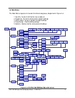
Page 19: ...dundancy HPA1 Hot Auto 1 255 Mute StbyMode Stby Select Switching Status 19200 38400 1 255 RS232 485 9600 4800 2400 Sys Address Normal Terminal BaudRate Interface ON OFF Factory User Set Clear Change P...

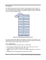
Page 20: ...n page The page shows HPA attenuation measured in dB Atten dB XX X with accuracy of 0 1dB Forward RF Power in dBm with resolution of 0 1dBm Alarms presence FAULT or None will be displayed depending on...

Page 21: ...FSW2 state of RF switch 2 possible values Pos1 Pos2 N A Fault State HPA online state possible values Online Standby Mute HPA mute state possible values Clear Set Prior Priority polarization select 1 2...

Page 22: ...status of the HPA s internal power supplies PS1 V main power supply 1 output voltage with resolution of 0 1V Normal output voltage should be in range of 11 to 13 V PS2 V main power supply 2 output vol...

Page 23: ...communication Available baud rates include 2400 4800 9600 19200 and 38400 The factory default Baud Rate is 9600 3 2 2 3 System Address Sets the network address of the controller if used on a RS 485 n...

Page 24: ...meters Fault on High Fault on Low Auxiliary Faults Allows the user to select the Action and the Fault Logic for fault conditions associated with the Auxiliary connections User can select the following...

Page 25: ...of the LCD and test the LED lamps on the front panel 3 2 5 1 Backup User Settings Allows the user to backup all settings to nonvolatile memory 3 2 5 2 Restore Restores saved settings either those from...

Page 26: ...26 203987 Rev A RCP2 1000 RM Remote Controller Operations Manual THIS PAGE LEFT INTENTIONALLY BLANK...

Page 27: ...mote SSPA These include Base plate temperature Power supply output voltage SSPA DC Current consumption Regulator output voltage RF Output level Gate Drive Voltage Muting Attenuation and internal redun...

Page 28: ...ult state signaling Front Panel LED Front Panel LCD Serial Protocol Field Form C contact closure 4 1 6 Low Forward RF Fault Fault is local to the RCP2 1000 RM unit Fault alerts the user when the outpu...

Page 29: ...switch fault state 4 1 10 Serial Connection Fault If serial communication can t be reliably established with remote SSPA unit RCP2 1000 will declare Serial Connection fault condition This condition s...

Page 30: ...brane Keypad 4 2 1 Digital Core Board The Digital Core Board is the heart of the redundant controller At the center of the digital core board is the Atmel AVR Mega 128 microcontroller The microcontrol...

Page 31: ...a large 2 line by 40 character alphanumeric display This provides an extremely user friendly interface The LCD is directly interfaced to the mi crocontroller via the address and data bus Virtually al...

Page 32: ...32 203987 Rev A RCP2 1000 RM Remote Controller Operations Manual 32 XXXXXX Rev Xyxyxyxy THIS PAGE LEFT INTENTIONALLY BLANK...

Page 33: ...M C utilities for Windows will seamlessly incorporate RCP2 1000 in its control setup In case of selecting Terminal mode protocol the RCP2 1000 provides remote menu access through HyperTerminal progra...

Page 34: ...ss field specifies the node for which the packet is intended It may be an individual or broadcast address The broadcast address is 0xFF This is used when a packet of information is intended for severa...

Page 35: ...sponse frame without change This byte serves as a request tracking feature 5 1 2 3 Command This one byte field tells the receiver how to use the attached data There are only four 4 possible values fo...

Page 36: ...byte position is replaced with the Error Status fields The various error codes are given in Table 5 3 Note that the Request and Response frames are different Tag Name DataTag Byte Value Minimum valid...

Page 37: ...to the response from the amplifier if the word size of the information is 16 bits or 2 bytes Each data word is placed in the frame with its least significant byte first All data with length of 2 byte...

Page 38: ...as Chksum 0 FOR byte_index 0 TO byte_index packet_len 1 Chksum chksum BYTE byte_index MOD 256 NEXT byte_index 5 1 4 Timing issues There is no maximum specification on the inter character spacing in me...

Page 39: ...top bit serial connection The SSPA will not echo back any incoming characters so local echo must be enabled on the remote terminal To establish a remote control session with the RCP2 the user must typ...

Page 40: ...setting up the PC configurations Start the Windows HyperTerminal Program default Windows location at Pro grams Accessories HyperTerminal Enter the name of your serial connection Compact Outdoor SSPA...

Page 41: ...e turn on Local Echo in the HyperTerminal application To do so select the following from the HyperTerminal menu File Properties Settings ASCII setup This will bring up a window similar to that shown i...

Page 42: ...d to work with the RCP2 in Terminal mode To es tablish a session with the RCP2 type UNIT 170 Note When using a RS485 connection avoid using the global address 170 Instead use the unique RCP2 address A...

Page 43: ...ev A 43 Appendix A Specifications The following pages comprise the specification sheet 203211 for the RCP2 1000 Remote Controller for Rack Mount SSPAs For the latest revision of this document refer to...

Page 44: ...44 203987 Rev A RCP2 1000 RM Remote Controller Operations Manual THIS PAGE LEFT INTENTIONALLY BLANK...

Page 45: ...ssible from the LCD Four navigation buttons and a separate Enter key allow the user to navigate the firmware menu on the LCD Separate buttons have been provided for frequently used functions Common fe...

Page 46: ...RCP2 1000 FRONT PANEL DESCRIPTION Characteristic Specification Configurations RCP2 1000 RM Remote Control Panel for RM SSPA Serial Communications RS 232 RS 485 2 wire Parallel I O Status Outputs Cont...

Page 47: ...includes two serial communications ports J4 and J5 The Main Serial Port J4 allows remote communication with a personal computer The Local Serial Port J5 allows a serial interface with a remote Rack M...

Page 48: ...ault Form C Relay NC 8 Opened on High Temperature Fault Form C Relay NO 26 High Temperature Fault Common 27 1 Standalone mode Closed on Regulator Low Voltage Fault 2 1 1 Redundancy Mode Closed on HPA...

Reviews: