background image

20  

  Single Side Burner Assembly 

GS-SB1 Single Side Burner Operator Manual 


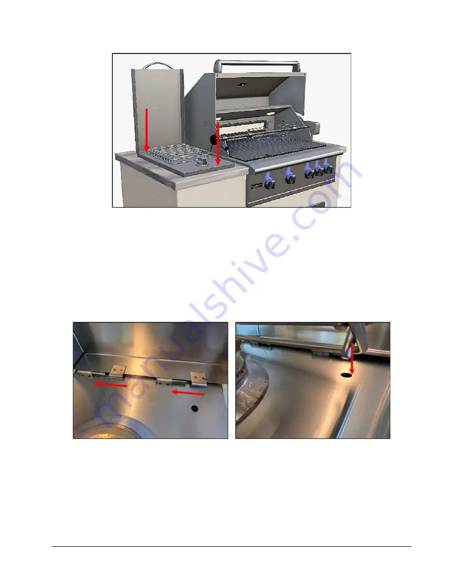
Figure 10 Position Single Burner into Place 

c.


Ensure nothing is binding below the burner unit  

6.


Check to ensure the burner unit is level and properly supported around the entire outside edge of 

the cut-out  


If the burner unit is not level or is unstable, use non-combustible shims under the outside lip to 

level and stabilize it  


Proper leveling of your burner unit is essential to its safe and proper operation; a non-level 

burner unit will result in erratic burner combustion, and inefficient, uneven heating 

7.


Ensure the burner cover is in place on the mounting pins (below left) 


Figure 11 Install cover and grate 

8.


Align the two grate mounting pins with the holes and insert into place (above right) 


Summary of Contents for GS-SB1

Page 1: ...GS SB1 Single Side Burner Operator Manual...

Page 2: ...FOR FUTURE REFERENCE You are responsible for checking updates and revisions available online at http www paradisegrillsdirect com owners Serial number ______________________________________ See inform...

Page 3: ...Items 10 LP Gas Cylinder 10 LP Cylinder Mount 10 Gas Regulator 11 Installation 11 Outdoor Rated Electric Cord 12 Safety Equipment 12 Covers 12 Grill Island Preparation 13 Paradise Grills Island Venti...

Page 4: ...urner 30 Stainless Steel Maintenance 30 Corrosive Environmental Conditions 31 Clean the Single Burner 31 Preventive Maintenance 32 Ventilation 32 Burner Inspection 32 Spiders and Other Insects 32 Trou...

Page 5: ...property damage An imminently hazardous situation which if not avoided will result in death or serious injury or property damage Operational Warnings All users must read this entire manual before atte...

Page 6: ...the vicinity of this or any other appliances EXPLOSION HAZARD Do not use the burner unit as storage area for flammable materials Keep area clear and free from combustible materials gasoline and other...

Page 7: ...ensure it specifies natural gas NG as the proper gas supply type Use the supplied NG regulator and NG flex line to connect the burner unit to the NG supply Use only pipe sealants that are specificall...

Page 8: ...g appliances Figure 1 LP Cylinder Valve Filling and Refilling LP Gas Cylinders Never use a dented rusty or damaged LP gas cylinder Never attempt to repair an LP cylinder The only way to safely resolve...

Page 9: ...the cylinder valve immediately and then a If the leak stops remove the regulator from the tank and reattempt the connection b If the leak persists turn off the tank valve and remove the regulator c I...

Page 10: ...Correct any leaks immediately See Leak Test on page 25 for more detail Transporting and Storing LP Gas Cylinder Do not store or use gasoline or other flammable vapors and liquids in the vicinity of th...

Page 11: ...ory Dimensions 12 5 8 W x 25 D x 12 3 8 H Total BTU Output 12 000 BTU Number of Burners 1 Orifice Size mm LP 1 05 mm Orifice Size mm NG 1 6 mm Drip Tray Stainless Steel Burner Aluminum and Brass Ignit...

Page 12: ...of Dangerous Goods See the LP cylinder collar for marking Figure 2 LP Gas Cylinder Requirements LP cylinder valve must have o Type 1 outlet compatible with regulator or burner unit o Safety relief val...

Page 13: ...r column pressure If installed with a NG grill the NG burner unit may be connected to the grill s regulated supply line via a T adapter or connected to its own separate NG supply line Installation Ope...

Page 14: ...ower supply The customer must supply an outdoor rated extension cord long enough to reach your chosen electrical outlet Use only a 12 gauge extension cord with a grounded 3 prong plug Outdoor extensio...

Page 15: ...ters to ensure the island s entire bottom edge on all sides is always at least 1 above the ground b Open gap spacing under the burner unit head and side burners if installed c Open gap spacing around...

Page 16: ...ier wind deflector or wind guard Winds directly hitting the back of the burner unit may cause unsafe and improper operation This burner unit is designed for outdoor use only DO NOT use this burner uni...

Page 17: ...he following planning considerations are provided as general information only You must consult with a licensed contractor to ensure safe and proper design construction ventilation and installation in...

Page 18: ...Burner is installed you should have clear access to the gas supply line including the gas piping or hose gas regulator gas cylinder and any shutoff valves A safety shutoff valve is required at the gas...

Page 19: ...hould rest on the lip of the frame Figure 8 illustrates sample cut out sizes for a grill island Here are some other considerations Ensure your grill island cavity is adequately vented Consult your loc...

Page 20: ...18 Grill Island Preparation GS SB1 Single Side Burner Operator Manual Single Side Burner Dimensions Figure 9 GS SB1 Dimensions...

Page 21: ...t If damages are unnoticed until the product is unpacked notify the delivery company immediately and file a concealed damage claim with them within 5 days of the delivery date Keep the box and shippin...

Page 22: ...he burner unit is not level or is unstable use non combustible shims under the outside lip to level and stabilize it Proper leveling of your burner unit is essential to its safe and proper operation a...

Page 23: ...e being supplied to the burner unit either NG or LP All gas installations connections conversions and adjustments must be performed by a qualified gas technician Figure 12 Single Side Burner Rating Pl...

Page 24: ...er must be marked in accordance with U S Department of Transportation CFR49 Part 173 Specifications for LP Gas Cylinders National Standards of Canada CSA B339 Cylinders Spheres and Tubes for the Trans...

Page 25: ...leaks as described in the Leak Test procedure below LP Gas The consumer must provide a regulator to connect the burner unit to the LP gas cylinder Ensure the regulator is equipped with a hose long en...

Page 26: ...clockwise until it stops 5 Remove the safety cap from the LP cylinder valve below left 6 Insert the regulator nipple into the LP cylinder valve keep the regulator in line with the LP cylinder valve t...

Page 27: ...nected or not whenever the gas cylinder is connected to the regulator and whenever any part of the gas system is disconnected or replaced The leak test should check all joints of the gas delivery syst...

Page 28: ...on page 34 6 Look below the burner Figure 18 and spray the orifice with soapy water to check for bubbles Figure 18 Burner Orifice Leak Test 7 Make note of the location of any leaks indicated by growi...

Page 29: ...ing your gas burner unit to prevent injury and appliance damage Do not leave an operating burner unit unattended Close supervision is necessary when this or any appliance is used near children Keep ch...

Page 30: ...d see Leak Test on page 25 All parts and components are properly in place Manual gas shut off valve is fully accessible The LP gas hose is clean and free of cuts wear abrasion or leaks Replace if nece...

Page 31: ...light the rear burner there is a loud click as the igniter produces the ignition spark 6 Watch the burner to confirm ignition if the burner does not light on the first try turn the knob OFF wait 2 mi...

Page 32: ...of chromium oxide protects stainless steel from corrosion Oxygen from the atmosphere combines with the chromium in the stainless steel to form a protective chromium oxide film This protection will be...

Page 33: ...stains use the products and processes described above Corrosive Environmental Conditions The 304 stainless steel materials used in the construction of your burner unit are rust and corrosion resistant...

Page 34: ...ar When lit the flame should have a bluish color to it If the flame has a tint of yellow adjustment can be made to obtain a blue flame and proper gas flow See the Troubleshooting section Inspect the b...

Page 35: ...b shaft is flat on top 2 A small brass screw inside the hole controls the air gas mix at the burners use a small flat head screwdriver to adjust a To decrease the flame size rotate to the left to allo...

Page 36: ...licensed plumber or gas professional 1 Shut off and disconnect the gas source from the burner unit 2 Remove the cover and grate set aside 3 Lift the burner out and set it on the top surface The ignit...

Page 37: ...Figure 22 right an arrow or the words IN and OUT should indicate the gas flow direction If regulator is installed the wrong way it will not work and gas won t flow Remove the old inlet and replace han...

Page 38: ...and adjust the setscrew shown in Figure 24 until the flame is 1 2 to 1 high c Align the knob opening with the shaft and press the knob back into position Figure 24 Flame Adjust Setscrew 12 Replace th...

Page 39: ...GS SB1 Single Side Burner Operator Manual Single Side Burner Diagram 37 Single Side Burner Diagram NOTE The cover handle is attached to the cover...

Page 40: ...e ORIGINAL PURCHASER S transfer of ownership of the burner unit to any other person or entity This Limited Warranty excludes and does not cover 1 oxidation rust corrosion discoloration staining or oth...

Page 41: ...GRILLS Paradise Grills shall not be liable to the ORIGINAL PURCHASER or any other person or entity for any incidental indirect special reliance general ordinary nominal pain and suffering lost profit...

Page 42: ...d barred To submit a warranty claim the ORIGINAL PURCHASER must submit a written description and photographs detailing the burner unit s damage or defect s along with a complete copy of the Final Sale...

Reviews: