background image

30  

  Operating the Grill 

GXL-45 Operator Manual 

Keep any electrical supply cord and fuel supply hose away from any 

heated surfaces and dripping grease. 
Use barbecue tools with wood handles and insulated grill mitts when 

operating the grill. 
The use of accessories, regulators, or components not recommended 

by the appliance manufacturer may cause injuries and will void 

warranties. 
Open the LP gas cylinder compartment door to inspect the gas supply 

hose before each use of the grill. If there is evidence of abrasion or 

wear, or the hose is cut, it must be replaced before putting the grill 

into operation. Refer to the 

Liquid Petroleum Gas

 section on page 26.  


Normal Lighting 

Prior to lighting your grill for the first time, verify that all of the following are complete and correct: 

 All packaging has been removed 

 Burner tubes are free of insects and insect nests, webs, etc. 

 Proper gas supply and regulator type are in place 

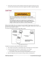
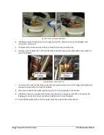
 The gas connection is complete, securely tightened, and leak tested (see 

Leak Test

 on page 27) 

 All parts and components are properly in place 

 Manual gas shut-off valve is fully accessible 

 The LP gas hose is clean and free of cuts, wear, abrasion, or leaks. Replace if necessary with a suitable UL, 

ETL, or CSA Listed part with 3/8” internally threaded connector


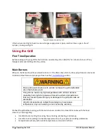
Follow these steps to light the burners, starting with the far-right burner:


1.


Open the gas supply valve 

2.


Open the hood 

3.


Keep your face as far away from the burners as possible 

4.


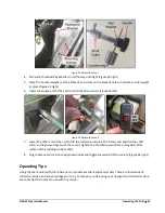
Push the far-right knob in, hold for 2-3 seconds for the gas to start 

flowing, then rotate the burner knob counterclockwise to the HI 

position  

5.


You will hear a loud click as the lighter produces a spark  

6.


Look and listen for the sound of the gas igniting; if the burner does not light on the first try, repeat 

immediately 

7.


If the burner does not light on the second try, push in the burner knob and rotate to OFF: 

a.


Open all access doors and drawers, and keep the grill hood open 

b.


Wait five minutes until the gas clears before attempting to light it again  

Summary of Contents for GXL-45

Page 1: ...GXL 45 Grill Professional Operator Manual...

Page 2: ...S FOR FUTURE REFERENCE You are responsible for checking updates and revisions available online at http www paradisegrillsdirect com owners Serial number ______________________________________ See info...

Page 3: ...oleum Cylinder Mount 9 Gas Regulator 10 Installation 10 Outdoor Rated Electric Cord 11 Safety Equipment 11 Grill Covers 11 Grill Island Preparation 12 Paradise Grills Island Ventilation 12 Clearances...

Page 4: ...rill 38 Stainless Steel Maintenance 38 Corrosive Environmental Conditions 39 Grill Exterior 39 Grill Interior 39 Cleaning the Drip Tray 40 Preventive Maintenance 40 Ventilation 40 Burner Inspection 40...

Page 5: ...s must read this entire manual before attempting to operate the grill Follow these safety precautions every time the grill is used This grill is for outdoor use only Do not operate in a building garag...

Page 6: ...as supplier or fire department immediately IF THE BURNER GOES OUT Gas will continue to flow out of the burner and could accidently ignite with risk of injury If during operation the flames go out and...

Page 7: ...illing of LP gas cylinders must be performed by qualified personnel in the LP gas industry Never store a spare LP gas cylinder under or near this appliance Never fill the LP gas cylinder beyond 80 per...

Page 8: ...r LP gas cylinder to excessive heat and always store the cylinder in an upright position Never store a spare LP cylinder indoors or within the grill enclosure When attaching components ensure all conn...

Page 9: ...ransporting or storing an LP gas cylinder Transport only one cylinder at a time Ensure the cylinder is secured in an upright position with the control valve turned off and the dust cover in place Stor...

Page 10: ...nition Piezo Ignition System Cooking Area 738 sq in Warming Area 224 sq in Drip Tray Stainless Steel Flame Tamer Stainless Steel w Ceramic Briquettes Included Grill Cover Optional Grill Lights Include...

Page 11: ...Dangerous Goods See the LP cylinder collar for marking Figure 2 LP Gas Cylinder Requirements LP cylinder valve must have o Type 1 outlet compatible with regulator or grill o Safety relief valve UL li...

Page 12: ...r connected to its own separate regulated supply line Installation Operating a gas cooking appliance without a proper regulator is dangerous and may cause serious bodily injury death and or property d...

Page 13: ...on cords should be used with outdoor products and are surface marked with suffix letter W and with a tag stating Suitable for use with outdoor appliances The maximum length allowed for the extension c...

Page 14: ...a Use the provided adjustable footers to ensure the island s entire bottom edge on all sides is always at least 1 above the ground b Open gap spacing under the grill head and side burners if installed...

Page 15: ...ck Follow all city and local codes Overhead construction Do not locate the grill under any unprotected combustible overhead materials At least 6 clearance is required between the grill and overhead co...

Page 16: ...requires its own vented compartment Firm level surface Use your grill only on a firm level surface This grill is not designed for use in or on a recreational vehicle and should not be installed or us...

Page 17: ...the lip of the frame Figure 7 illustrates sample cut out sizes for a grill island Here are some other considerations Ensure your grill island cavity is adequately vented Consult your local licensed p...

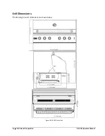
Page 18: ...16 Grill Island Preparation GXL 45 Operator Manual Grill Dimensions The GXL 45 grill outer dimensions are shown below Figure 8 GXL 45 Dimensions...

Page 19: ...and remove the rotisserie spit rod and the Styrofoam spacers 2 Remove the grill from the box and place on a solid surface 3 Remove the plastic wrap cardboard spacers Styrofoam spacers and zip ties fro...

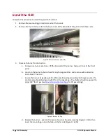
Page 20: ...the burner then pull it out of the front panel b Look into the burner tube to check for any foreign particles and remove with cold water and a brush if needed c Ensure the burner air gap Figure 10 le...

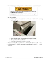
Page 21: ...ace 4 Before installing the grill in any island cut out measure to ensure the opening is not bigger than the outside frame of the grill Figure 12 the grill edges must rest on the lip of the frame Figu...

Page 22: ...a Position the grill so it is two thirds of the way into the cut out with the outside edges resting on the cut out edges Figure 14 Position Grill into Place b Ensure the gas line and electrical cable...

Page 23: ...DO NOT DISASSEMBLE THESE ITEMS 3 Seat each flame tamer in place on support pins on each end with briquet side up Figure 16 Figure 16 Flame Tamer Installation a There are four pairs of pins on each sid...

Page 24: ...ch side of the grill near the top Figure 19 Insert Warming Rack 7 Connect the LED light electrical cable to the power supply Figure 20 Connect Power Supply a Align the grill plug with the power supply...

Page 25: ...in use and before cleaning Do not operate any outdoor cooking gas appliance with a damaged cord plug or after the appliance malfunctions or has been damaged in any manner contact Paradise Grills to d...

Page 26: ...ty damage Operation without a proper gas regulator will void all grill warranties Grills operated with NG must be installed with the NG regulator supplied with the grill and set to 4 0 water column pr...

Page 27: ...the grill forward as needed to gain access to the regulator and gas connection point in the rear With the grill slid forward support the front edge to prevent the grill from tipping and falling out of...

Page 28: ...ebris Do not insert a tool or foreign object into any gas valve which could cause damage and cause a leak Leaking propane may result in explosion fire severe personal injury or death 2 Ensure all gril...

Page 29: ...m a leak test before first use and at least once a year whether the gas supply cylinder has been disconnected or not whenever the gas cylinder is connected to the regulator and whenever any part of th...

Page 30: ...e with soapy water to check for bubbles Figure 28 Burner Orifice Leak Test 7 To leak test the rear burner orifice open the rear panel to access the orifice Figure 28 right and spray with soapy water t...

Page 31: ...ile lighting the grill or checking the gas supply connections NEVER cover slots holes or passages in the grill bottom or cover an entire rack with material such as aluminum foil Doing so blocks air fl...

Page 32: ...e are in place The gas connection is complete securely tightened and leak tested see Leak Test on page 27 All parts and components are properly in place Manual gas shut off valve is fully accessible T...

Page 33: ...er and a brush to remove any built up grease and char from grilling Manual Lighting A manual lighting tube is provided Figure 29 left for use in case the ignitor stops working The tube is located at t...

Page 34: ...ection Ensure all open burners are lit and do not leave the grill unattended when the burners are lit This grill can reach very high temperatures with all main burners operating burning fat or grease...

Page 35: ...ut of control evacuate the area immediately and call the fire department Rear Infrared Burner NOTE REMOVE THE WARMING RACK BEFORE USING THE REAR INFRARED BURNER FAILURE TO DO SO WILL DAMAGE OR WARP TH...

Page 36: ...r food or grill components Rotisserie Setup Rotisserie components require a simple assembly as follows Figure 32 Rotisserie Components 1 Attach the motor bracket to the outside of the grill hood the m...

Page 37: ...other end of the spit rod to the rotisserie cutout in the frame and position the shaft collar so the groove aligns with the cutout tighten the thumbscrew with the end against a flat surface of the rod...

Page 38: ...ottom then you have balanced your food nicely well done o If the rod easily spins and the food rotates toward the floor you must balance the load using the counterbalance on the spit rod o Loosen the...

Page 39: ...emperature reading won t be accurate Always use grill gloves to handle anything hot including the food Unless your recipe says otherwise keep the grill hood closed as much as possible throughout the c...

Page 40: ...rotects stainless steel from corrosion Oxygen from the atmosphere combines with the chromium in the stainless steel to form a protective chromium oxide film This protection will be reduced by any cont...

Page 41: ...and left on the grill corrosive elements such as chlorine in the air high salt content air fertilizers pesticides corrosive cleaning solutions and masonry dust and debris may cause the stainless steel...

Page 42: ...vailable from Paradise Grills International Inc Contact us at 800 604 2023 for assistance At least twice a year conduct the following inspections to ensure safe grill operation Ventilation Ensure gril...

Page 43: ...rs and other insects can nest in the burners and orifices of this and any other outdoor products This can create a dangerous condition that can cause a fire behind the valve panel damaging the grill a...

Page 44: ...l flat head screwdriver to adjust a To decrease the flame size rotate to the left to allow more air b To increase the flame size rotate to the right to reduce the air c Make incremental changes Figure...

Page 45: ...lame and adjust again as needed 5 Repeat for all burners as needed Confirm Gas Type If the air mixers have been set and the grill flame is still not performing as expected check to ensure the primary...

Page 46: ...ve all cooking grates and flame tamers to expose the main burners 3 If needed remove the cotter pins from the far end of each burner tube see Install the Grill 4 Lift the far end of a burner slide the...

Page 47: ...is installed the wrong way it will not work and gas won t flow Remove the old inlet and replace hand tight with new do not overtighten Figure 41 Gas Inlets 8 Connect the gas supply per the Connection...

Page 48: ...ng the main burner orifices and before turning on the gas to complete the leak check 1 Remove the access plate as shown in the Confirm Gas Type procedure 2 Use a 3 8 open end wrench to loosen and remo...

Page 49: ...BEZEL 1 4 HOOD HANDLE 2 5 IR REAR BURNER 1 6 BACK COVER 1 7 IR IGNITER COVER 2 8 WARMING RACK 1 9 IGNITER 2 10 LIGHT 4 11 STAINLESS STEEL FLEX LINE 1 12 ELECTRODE WIRE 1 13 FIREBOX 1 14 STS BURNERS 4...

Page 50: ...IRE 1 26 REAR BURNER VALVE 2 27 MAIN BURNER VALVE 4 28 GAS MANIFOLD ASM 1 29 NG OR LP REGULATOR 1 30 TRANSFORMER 1 ROTISSERIE ASSEMBLY A MOTOR 1 B MOTOR BRACKET 1 C SPIT ROD 1 D FORK 2 E THUMBSCREW 3...

Page 51: ...GXL 45 Operator Manual Parts Diagrams 49 Grill Diagram...

Page 52: ...is void upon the ORIGINAL PURCHASER S transfer of ownership of the grill to any other person or entity This Limited Warranty excludes and does not cover 1 oxidation rust corrosion discoloration stain...

Page 53: ...S Paradise Grills shall not be liable to the ORIGINAL PURCHASER or any other person or entity for any incidental indirect special reliance general ordinary nominal pain and suffering lost profits exem...

Page 54: ...d To submit a warranty claim the ORIGINAL PURCHASER must submit a written description and photographs detailing the grill s damage or defect s along with a complete copy of the Final Sales Agreement e...

Reviews: