6
______________________________________________________________
< >
(info key)
Button
Displays help information about a menu or action. In the main screen it displays
the Menu of Access Level 1 (informational).
<ARROW
KEYS>
Button
Navigate through menus, lists and log.
Table 1.
Keyboard description
4. Bus connection
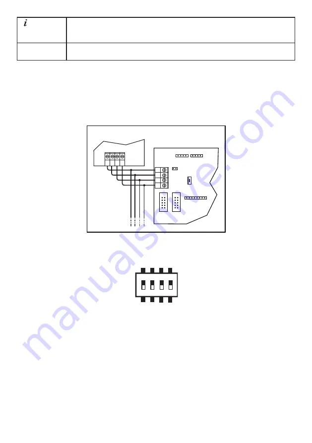
If the system has modules other than the ones inside the main cabinet, they must be
connected with the 4 wire bus. Each module has a 4 way terminal block for this pur-
pose. The correct connection is show in Figure 2. Take great care not to mix the data
wires with the power wires as permanent damage may be caused.
B
-
+
A
MAIN BOARD
Stand Alone LCD
Keypad/Repeater
B GND
Vbus A
Next Module
Figure 2.
BUS connection
5. Setting keypad modules IDs
1 2 3 4
SW1
ON
Figure 3.
Set of dip switches
All modules except the power supply units (PSUs) have a set of dip switches (Figure 3)
that controls their address on the bus system.
It is very important to set a unique address to each keypad. Follow the rules below to
set a correct set of addresses:
•
The panel’s keypad board ID must be set as ID=0. Set the dip switches SW1-1 to
SW1-4 to OFF.
•
Each “Stand Alone” and “On Panel” keypad must have a unique ID from 1 to 8.
See Table 2 for IDs against dip switch settings.


