11
Matrix2000 repeaters
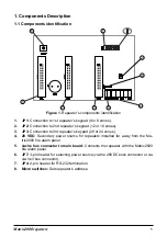
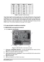
“DEF” pin headers:
1.
Reset the MRTCP-IP module to default settings.
Ethernet connector
2.
.
4-wire bus connector to main board:
3.
Connects the MRTCP-IP module with the
Matrix2000 fire alarm panel.
12 to 24 VDC:
4.
Secondary power source for MRTCP-IP modules installed far away
from the Matrix2000 fire alarm panel
APB:
5.
3-pin header for selecting power source (via the 12-24VDC bock connector or
via 4-wire Vbus connector).
Connector:
6.
Connects the MRTCP-IP
module with the Matrix2000 fire alarm panel’s
main board via flat cable.
6.2.2 General Description
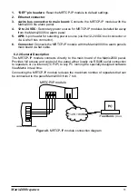
The MRTCP-IP module connects directly to the main board of the Matrix2000 panel.
Provides full access and control of the panel either locally via RS485 serial connection
to repeaters or via internet (TCP/IP) to any PC running the specially designed software
ViewMatrix in real time.
Connecting the MRTCP-IP module reduces the maximum number of repeaters that can
be connected to the panel Matrix2000 from 7 to 6.
MRTCP/IP module
ViewMatrix
plus
Figure 8.
MRTCP-IP module connection diagram
Summary of Contents for MATRIX RPT 12Z
Page 4: ......
Page 15: ......
Page 16: ...Document Part Number MATRIXREP IEN1 CPD version 1 0 revision 0 March 2013 ...


