5
Matrix2000 repeaters
1. Components Description
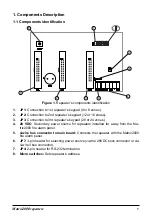
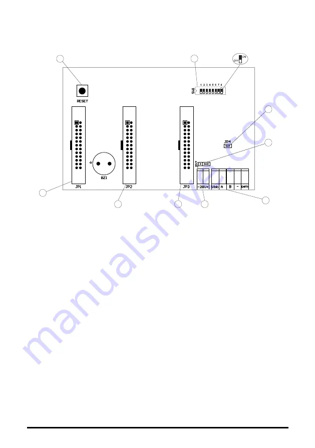
1.1 Components identification
1
8
2
3
4
5
7
6
7
Figure 1.
Repeater’s components identification
JP1:
1.
Connection to 1st repeater’s keypad (4 or 8 zones).
JP2:
2.
Connection to 2nd repeater’s keypad (12 or 16 zones).
JP3:
3.
Connection to 3rd repeater’s keypad (20 or 24 zones).
28 VDC:
4.
Secondary power source for repeaters installed far away from the Ma-
trix2000 fire alarm panel.
4-wire bus connector to main board:
5.
Connects the repeater with the Matrix2000
fire alarm panel.
JP7:
6.
3-pin header for selecting power source (via the 28VDC bock connector or via
4-wire Vbus connector).
JP4:
7.
2-pin header for RS-232 termination.
Micro switches:
8.
Sets repeater’s address.
Summary of Contents for MATRIX RPT 12Z
Page 4: ......
Page 15: ......
Page 16: ...Document Part Number MATRIXREP IEN1 CPD version 1 0 revision 0 March 2013 ...


