background image

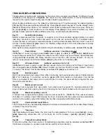
TROUBLE DISPLAY/MONITORING 

Trouble status is continuously monitored by the panel. It can recognize and display 10 different trouble
conditions on the keypad or in 

Espload, and report 8 to the central station. (To send "trouble status

reports" to the central, 2-digit trouble report codes should be programmed.)

When trouble conditions occur, the [

TRBL

key illuminates and if "trouble warning" is enabled (address

210, key [9]) the keypad will beep intermittently. Press [

TRBL

to switch keypad to "trouble display" mode.

[

TRBL

key flashes. Keys that are "on" indicate current trouble conditions and those in memory. Press any

key except [2

ND

to return keypad to normal display. Press [2

ND

to view current troubles only. Press

[

CLEAR

to erase previous trouble conditions in memory, and to silence trouble warning.

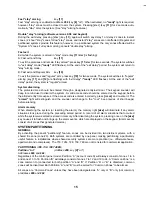
Key [1] 

No battery/low battery

Battery is disconnected from the panel, or capacity is low. Panel conducts dynamic battery test under
load every minute for a 4 sec. period, and every hour for a 64 sec. period. Key [1] "on" indicates battery
is disconnected, or it should be replaced because it won't provide adequate back-up current in event of
AC loss. Trouble indicator [1] also comes "on" if battery voltage drops to 10.5 volts while panel is running
on battery power (with no AC).
Note: System can be programmed to inhibit arming if no/low battery condition exists - Address 210, key [4].

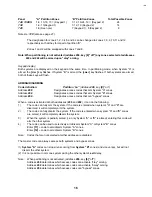
Key [2]

Power failure

(software versions 1.4 and beyond only)

Inadequate AC power is going to panel and/or power supply is unable to charge battery and/or power
supply voltage exceeds 14.9V. (Report can also be sent to central, and “power failure” report delay time
is programmable at address 252. Delay duration can be from 000 - 255 minutes; default = 30 min.) To
remove “power failure” from trouble display, [2

ND

key should be “on” at address 210.

Key [3]

AC power failure

(software versions prior to 1.4)

Inadequate AC power is going to panel. (Report can also be sent to central, and "AC failure" report delay
time is programmable at address 252. Delay's duration can be from 000-255 minutes, default = 30 min.)
To remove "AC failure" from trouble display, at address 210[2

ND

key should be "on". 

Key [4] 

Bell disconnect

Bell is not connected to bell output. Note: When connecting bell to optional relay output, trouble indicator
[4] is "on" constantly. To avoid this, connect a green (1K

W) 

EOL resistor on bell output. If an internal

siren is connected to bell output, and an external siren to relay, the panel will only recognize the exis-
tence of the internal siren.

Key [5]

Maximum bell current

Processor has recognized that, upon alarm, bell output current exceeds 3A., causing automatic shut-
down of bell output. After opening the short or reducing the load, bell shut-down will end upon bell cut-off.

Key [6]

Maximum auxiliary current

Processor has recognized that auxiliary output current exceeds 1A. (748ES-3A) This causes automatic
shut-down of  auxiliary output. After opening the short or reducing the load, power will be automatically
restored to the auxiliary output after battery test has been conducted (within 60 seconds).

Key [7]

Communicator report failure

The control panel has unsuccessfully attempted to initiate communication with the central. Report failure
is stored in "event list" memory.

Key [8]

Timer loss

After total battery/AC power failure, the timer must be reprogrammed. To do so, press [

ENTER

+ code +

[

MEM

], followed by correct time (00 - 23 for hours, 00 - 59 for minutes) + [

ENTER

[

ENTER

[

TRBL

+

[

CLEAR

].

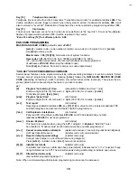
Key [9]

Tamper/zone wiring failure

A zone line cut/line short has occurred. Tamper/wiring recognition must be activated at address 208 if
this feature is required. 

EOL

resistors must also be used for zone connection.

18

IM8

Summary of Contents for Esprit 718

Page 1: ...Installation Manual P R D O X P R D O X S E C U R I T Y S Y S T E M S S E C U R I T Y S Y S T E M S ESPRIT 718 728L 728 738 748 748ES 718 728L 728 738 748 748ES IM8 960715 0000...

Page 2: ...ended application 2 If the installation is a FIRE ALARM application refer to NFPA Standard 74 for details on locating smoke detectors There must be at least one UL Listed Indoor Fire Alarm Warning Sig...

Page 3: ...K UP 9 BATTERY TEST 9 ZONE WIRING CONFIGURATIONS AND OPTIONS 9 12 LOOP CONFIGURATIONS AND ZONE CONNECTION 9 ATZ Zone Identification Table 9a Resistor Guides 9a Advanced Technology Zoning 10 11 Single...

Page 4: ...ERS 22 PC download telephone number 22 Central station telephone numbers 22 System account codes 22 REPORTING CODES 23 24 General 23 Arming codes disarming codes 23 Zone alarm codes 23 Zone restoratio...

Page 5: ...on Tamper wire Fault 30 No tamper bypass 30 Only bypass code reported on bypass arming 30 Advanced Technology Zoning ATZ 30 Audible Trouble Warning 30 Keypad zone supervision 30 31 ZONE DEFINITION 31...

Page 6: ...phone line monitor and fast formats Model 718 does not provide fast formats Esprit 718 UL ULC listed Up to 5 hardwire zone control panel Comprised of 3 onboard single zone inputs up to 2 additional ke...

Page 7: ...er on a single pair of wires as well as wire fault recognition ATZ simplifies the task of meeting the zone requirements of any application and at the same time reduces installation costs 5 Advanced Te...

Page 8: ...nd or report only Programmable Outputs Almost any control panel status situation may be used to activate the Esprit s programmable outputs Once a panel status mode is selected for a PGM to follow the...

Page 9: ...ttery Charger 360mA with active Battery test Aux power 400 mA UL ULC installations Fuseless electronic shut down at 1A Automatic restore Bell Out 1A Fuseless electronic shut down at 3A Automatic resto...

Page 10: ...al is the connection for the positive lead Bell terminal is the connection for the neg ative lead The bell output supplies 12V upon alarm It can support two 20 watt or two 30 watt sirens Above 1A batt...

Page 11: ...blocked if the battery test fails if programmed Test failure causes trouble indicator key 1 to illuminate indicating that battery capacity is insufficient When the panel runs on battery power with or...

Page 12: ...mper signals SINGLE ZONE connection without EOL resistor N C contacts address 208 key MEM on key 10 off default key 11 off default address 210 key 8 off N C contacts see Figure 1 Note Keypad zones alw...

Page 13: ...ition wire fault short circuit recognition N C contacts address 208 key MEM off key 10 key 11 address 210 key 8 on Tamper fault transmits separate code Each zone transmits separate alarm code Wire fau...

Page 14: ...our the tamper definition follows the audible silent alarm arm definition of the 24 hour zone Tamper recognition addresses Tamper report and restoration codes should be programmed at addresses 191 and...

Page 15: ...unting Dead Air Space The smoke from a fire generally rises to the ceiling spreads out across the ceiling surface and begins to bank down from the ceiling The corner where the ceiling and wall meet is...

Page 16: ...ature The AWAY key should be pressed followed by a valid access code address 202 The ready light does not have to be on but all open zones must be bypass enabled addresses 236 and 238 Once the exit de...

Page 17: ...allotted entry time expires If the access code is entered incorrectly press CLEAR and re enter it The armed light will extinguish and the sounder will change to the CONF beep series of short beeps be...

Page 18: ...that can bypass zones When a code is activated at both addresses 200 and 202 it can do the following 1 The code can fully arm the system If the code is entered when systems A and B are disarmed it wi...

Page 19: ...nes have been bypassed To cancel the zone bypass status just entered press BYP user code CLEAR Zone bypasses are automatically cancelled every time the system is disarmed except in 24 hour zones If a...

Page 20: ...ve power failure from trouble display 2ND key should be on at address 210 Key 3 AC power failure software versions prior to 1 4 Inadequate AC power is going to panel Report can also be sent to central...

Page 21: ...key listed below corresponding to the feature you wish to enable KEY 9 Program auto arming time accessible to Master and User 1 only Enter two digits 00 to 23 for hours 2 digits 00 to 59 for minutes...

Page 22: ...ECIAL TIMING FUNCTIONS The time programmed at addresses 245 246 can be used to 1 Auto arm the system and if programmed transmit the arming code at address 188 SECTION 32 2 Specify the time of day for...

Page 23: ...nel will not answer Default value is 2ND 8 UPLOAD PANEL IDENTIFIER Addresses 001 002 DIRECT ADDRESS This four digit code identifies the control panel to the PC before uploading can be initiated Each p...

Page 24: ...uffer is full and call PC feature is enabled 208 2ND on this number will be dialed in order to download the event list Related features Upload Panel ID 001 002 PC password 003 004 Central Station Tele...

Page 25: ...ming the control panel to the central monitoring station Each user code can be assigned an arm disarm report code Espload and the master code can be assigned a report code at addresses 188 189 see spe...

Page 26: ...Espload Using Espload to disarm the system will generate a special report code Disarm with master code Using the master code to disarm the system will generate a special report code Two digit hexa cod...

Page 27: ...t at 514 491 2313 SYSTEM OPTIONS Default off for addresses 200 242 Code priority Addresses 200 to 204 Key 1 represents user code 1 2 2 3 3 4 4 5 5 6 6 7 7 8 8 9 9 10 10 11 11 12 12 BYP 13 MEM 14 TRBL...

Page 28: ...ay be programmed to arm at the same time every day Program both the hour and minute addresses 245 246 for arming This will also be the auto test report time if enabled A late closing code may be progr...

Page 29: ...on reporting or disarm On split reporting silent zones panic are reported to Telephone 1 The Contact ID report for all zones is burglary Dialing pulse rates for Espload Address 206 key 10 This selecti...

Page 30: ...y key 7 Double reporting dialing procedure 2 2 2 2 2 2 2 2 communicator report failure 1 1 1 1 1 1 1 1 communicator report failure Note To stop communication attempts until the next reportable event p...

Page 31: ...stay arm system for 2 seconds User access code length Address 208 Key 9 off 6 digit user access codes and installer code Key 9 on 4 digit user access codes and installer code Tamper wire Fault Defini...

Page 32: ...ilure Low Voltage is present Arm inhibit on Tamper wire Fault Address 210 key 5 Key on system will not arm if Tamper fault is present MUST BE RESET BY INSTALLER BEFORE SYSTEM CAN BE ARMED AGAIN No tam...

Page 33: ...armed Zone 3 becomes a fire zone when defined 24 hour Zone 12 for software versions prior to 0 98 The fire zone should always be connected with a green 1K OHM EOL resistor If there is a line short in...

Page 34: ...m the system on time if enabled at address 206 key 5 3 Send a late to close code programmed at address 190 If the system is not armed at this time and if address 253 no movement time is disabled by pr...

Page 35: ...l reset without powering down the installer code is required Panel reset without power down 1 Connect a jumper between reset jumper pins 2 Press ENTER installer code STAY 3 Remove jumper The factory d...

Page 36: ...cations to maintain uninterrupted service GENERAL This equipment shall not be used on coin telephone lines Connection to party line service is subject to state tariffs RINGER EQUIVALENCE NUMBER REN Th...

Page 37: ...CTIONS CONCERNANT LE RACCORDEMENT DE MAT RIEL L tiquette d Industrie Canada identifie le mat riel homologu Cette tiquette certifie que le mat riel est conforme certaines normes de protection d exploit...

Page 38: ...configurations and zone connection 9 Master and user codes 19 No movement report 20 No tamper bypass 30 One Key arming enable 29 One key user programming commands 19 Only bypass code reported on bypas...

Reviews: