HV8D - page 1
HV8D: 8-Channel High Voltage Output Module
Description
Driven by the V32 main controller’s 4-wire communication
bus (Multibus), the HV8D has 8 outputs that can drive
incandescent lights of up to 10A per channel @ 110Vac/
230Vac (on/off operation), or 0.5hp shutter motors of up to
8A per channel @ 110Vac/230Vac (variable positions).
The HV8D was designed specifically to offer unique control
of shutters that can open/close shutters or blinds to multiple
positions and not only fully open or fully closed. When used
with the Imperial Dimmer Wall Switches, the system
provides up to 32 shutter positions. A short, one-time
calibration is required per shutter for efficient control.
The HV8D will also feature a Local Bus (coming soon) to
control shutters without the need of the Imperial system.
Imperial Dimmer Wall Switches that are connected to the
HV8D's local bus are independent from the rest of the
system and can control the local outputs.
Features
•
8 high-voltage relay outputs: incandescent lights (110/
230V, 10A) or 0.5hp motors (110/230V, 8A)
•
2 operating modes: relay mode and shutter mode (pair
two outputs for up/down control of a shutter)
•
Built-in calibration mode for precise open/close timing
•
4 emergency stop inputs per shutter motor (e.g. IR
beam stops the motor when motion is detected).
•
Global Up/Down input (e.g. 2-way momentary switch
controls all connected shutter motors simultaneously)
•
Remote firmware upgradeability via bus
•
DIN rail design with manual control for outputs, on-
board status display, and removable terminals
•
Programming via BabyWare software
•
4 wire connection to the Imperial Multibus with up to
900m (3000ft) distance
•
Bi-directional Locate feature from module to software
and vice versa
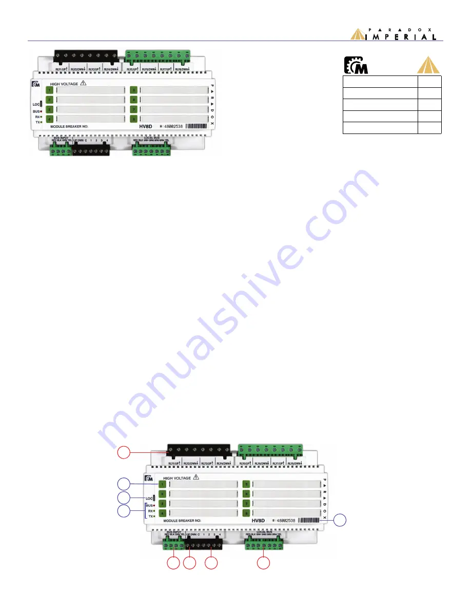
Overview
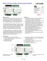
1) Manual output control and status buttons
2) Module Locate feature activation (see "Bi-directional
Locate Feature” on page 4)
3) Multibus status LEDs
4) Product serial number
A) High-voltage relay outputs 1 to 8. Each output pair can
be set in Shutter Mode to provide an UP and DOWN
output for one shutter.
B) 4-wire Multibus connection
C) Global up/down connection for all shutter motors
D) 4 emergency stop inputs
E) Local bus connection (future use)
TM
DRAFT
Installation/Wiring:
??
Programming 1:
??
Programming 2:
??
Testing:
??
Total Time:
??
A
2
3
B
1
4
For items A to E, refer to "Wiring”
on page 2.
C
D
E
For LED status, refer to "LED
Feedback” on page 3.

