OMNDCT1-BI01
Thank you for choosing the
Paradox®
Omnia™ OMN-DCT1
Wireless Door Contact for your
professional security applications.
You have selected one of the most
advanced wireless door contacts
available on the market today.
Every wireless door contact is
100% quality-control tested using
computerized test equipment,
guaranteeing proper operation and
unit durability. The OMN-DCT1
Wireless Door Contact includes the
following:
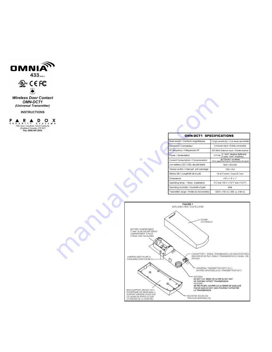
• Two high sensitivity reed switches
• Universal transmitter input
• Low battery / signal transmission
red LED indicator
• Built-in antenna
• Tamper switch
• Three “AAA” alkaline batteries
(included)
• Range: 500 ft (150m)
LOCATION & MOUNTING
The door contact is used to protect
doors and windows along the
perimeter. Typically, a magnet is
mounted on a door or window and
the transmitter is mounted on the
door frame or windowsill. When
installing transmitters, please be
sure there is at least 1ft (30cm)
between each transmitter and 5 feet
(1.5m) between the transmitters
and the receiver. When the magnet
moves approximately a half an inch
from the reed switch, the transmitter
will send an open zone signal.
When the magnet returns to within
a half an inch of the reed switch, the
transmitter will send a zone restore
signal. The transmitter comes with
two reed switches allowing you to
place the transmitter either
vertically or horizontally (refer to
Figure 2 on the reverse side of
these instructions). Simply place
the magnet in line with the reed
switch you wish to use. The other
reed switch and the universal
transmitter input (see below) will
automatically be disabled.
WARNING:
Do not cut, bend or alter the
antenna. Avoid mounting the door
contact near or on metal as this
may affect transmission.
UNIVERSAL TRANSMITTER
INPUT
The door contact can also be used
as a universal transmitter. A switch
or other security device can be
connected to the universal
transmitter input terminals in order
to provide wireless transmission of
the device's open/closed status to
the receiver. If one of the reed
switches is being used, the
universal transmitter input will be
disabled.
JUMPERS
The door contact is equipped with
two jumpers used to set the Check-
in Supervision mode of the door
contact. Refer to Figure 2 on the
reverse side of these instructions
for jumper locations.
WARNING:
After changing jumper settings,
you must reset the unit. To reset
the unit, remove the batteries,
press and release the tamper
switch (refer to Figure 2 on reverse
side) and wait 60 seconds. Re-
insert the batteries while verifying
proper polarity.
J1 - Check-in Supervision Time
Value
ON
= 12 (default)
OFF
= 6
J2 - Check-in Supervision Base
Time
ON
= hours (default)
OFF
= minutes
For example, to obtain a check-in
Supervision Timer of 6 hours, set
J1= OFF and J2=ON.
WARNING:
Use the same supervision setting
as in the Omnia Wireless Receiver
module.
POWERING THE UNIT
Verifying proper polarity, insert
three “AAA” batteries into the door
contact’s battery compartment. To
replace the batteries, remove the
old batteries, then press and
release the tamper switch (refer to
Figure 2 on the reverse side of
these instructions) and wait 60
seconds in order to re-initialize the
unit. Insert new batteries while
verifying proper polarity.
WARNING:
After inserting the batteries in the
door contact, a power-up sequence
will begin (lasting 10-20 seconds)
during which the door contact will
not detect an open zone or tamper.
SIGNAL STRENGTH TEST
In order to verify the receiver's
reception of the door contact’s
signal, perform a signal strength
test as described in the Omnia
Receiver Module’s Reference and
Installation Manual before finalizing
the installation of the door contact.
Prior to performing the test, verify
that the batteries have been
installed in order to power the door
contact. Also, verify that the door
contact has been assigned to a
zone according to the instructions
provided in the Omnia Receiver
Module’s Reference and Installation
Manual. If the transmission is weak,
relocating the transmitter by a few
inches can greatly improve the
reception.
RED LED INDICATOR
The red LED indicates the following:
Low Battery
The door contact performs a battery
test every 12 hours and if a battery
voltage of 3.1V or less is detected
during this test, the red LED will
flash at 5 second intervals.
Signal Transmission
The red LED indicator light will blink
rapidly when the door contact
transmits a signal to the Receiver.
FUNCTIONAL TEST
Once all door contacts have been
installed and a signal strength test
performed, set the control panel in
"Installer Test Mode" (see
appropriate Paradox Control
Panel’s Reference and Installation
manual). Open and close all doors
and windows. When a door or
window is opened, the bell will
squawk to indicate that it is
functioning.
WARRANTY
The Seller warrants its products to be free from
defects in materials and workmanship under
normal use for a period of one year. Except as
specifically stated herein, all express or implied
warranties whatsoever, statutory or otherwise,
including without limitation, any implied warranty of
merchantability and fitness for a particular purpose,
are expressly excluded. Because Seller does not
install or connect the products and because the
products may be used in conjunction with products
not manufactured by Seller, Seller cannot
guarantee the performance of the security system.
Seller obligation and liability under this warranty is
expressly limited to repairing or replacing, at
Seller's option, any product not meeting the
specifications. In no event shall the Seller be liable
to the buyer or any other person for any loss or
damages whether direct or indirect or
consequential or incidental, including without
limitation, any damages for lost profits, stolen
goods, or claims by any other party caused by
defective goods or otherwise arising from the
improper, incorrect or otherwise faulty installation
or use of the merchandise sold.
Note: The warranty does not apply to the
Alkaline batteries provided with the unit.
P
R
IN
T
E
D
I
N
C
A
N
A
D
A
-
0
8
/0
1


