background image

 Page 8

Overview

The following table provides a description of the PCS200 Communicator 
Module LEDs.

RX

Flashing green: receiving data

TX

Flashing green: transmitting data

Error

Red: module is not communicating with control panel. 
LED will be lit on power-up until a connection has been 
established.

N/A

Future use

SIM Card 
Error

Red: SIM card is not present or communication cannot 
be established via the SIM card

Signal 
Strength

Indicates the quality of the signal
1 LED lit: weak signal
3 LEDs lit: strong signal

GPRS

Green: established a GPRS connection on the GSM 
network
Flashing green: transmitting GPRS data

GSM

Green: connected to the GSM network

Summary of Contents for PCS200

Page 1: ...PCS200 Communicator Module V2 2 Reference and Installation Manual...

Page 2: ...adox Ltd or its affiliates in Canada the United States and or other countries For the latest product approvals such as UL and CE please visit www paradox com 2012 Paradox Ltd All rights reserved Speci...

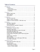
Page 3: ...sion Installation Optional 14 Configuring the PCS200 15 Modifying the Frequency Band 15 Bandwidth Saver Mode 15 Configuring GSM Network Provider Information 16 Configuring WinLoad Access 16 Programmin...

Page 4: ...ser SMS Programming with MG SP E Series 24 View GSM IP Information 25 Viewing GSM IP Information with Digiplex EVO 26 Viewing GSM IP Information with MG SP E Series 26 Pre Defined Text Messages 27 Ala...

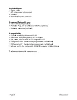
Page 5: ...res Report events to the IPR512 GPRS IP Monitoring Receiver via GPRS or to a landline receiver via GSM Fast upload download with WinLoad or NEware via a GPRS connection Firmware upgrades via GPRS or d...

Page 6: ...e Module VDMP3 optional Antenna extension optional Compatibility EVO48 and EVO192 panels V2 02 K641 and K641R keypads V1 51 or higher SP series V3 42 with K32LCD keypads V1 22 E55 panels V3 0 labels t...

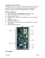
Page 7: ...m components System Components 1 SIM card slot supports standard GSM provider SIM cards 2 System LEDs refer to LED Feedback on page 7 3 Antenna cable connector 4 Mounting holes used to mount the PCS20...

Page 8: ...el LED will be lit on power up until a connection has been established N A Future use SIM Card Error Red SIM card is not present or communication cannot be established via the SIM card Signal Strength...

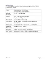
Page 9: ...70 80 140 170 MHz Antenna Gain 3dBi impedance 50 ohm Input power 2W peak power Power Input 12 Vdc from control panel Consumption 80 mA Standby max 600 mA during GPRS GSM transmission Dimensions 12 2c...

Page 10: ...network provider Note Prior to setting up your PCS200 it is important that the Personal Identification Number PIN of the SIM card be disabled Refer to your cellular phone s manual for more informatio...

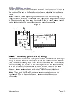
Page 11: ...nly The Paradox Voice Module VDMP3 can send pre recorded voice messages on up to 8 phone numbers to report alarms via the GSM cell phone network This is done by mounting the VDMP3 directly on the PCS2...

Page 12: ...tion Valid range values are between 85 to 100 anything outside of this range will reset the command to 85 To adjust the GSM volume the following SMS command must be sent P admin VOLOUT volume value e...

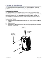
Page 13: ...ant to mount the metal box as far away as possible from any electronic equipment Ensure that the metal box is mounted as high as possible to ensure protection from RF interference and to maximize the...

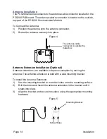
Page 14: ...re 4 Antenna Extension Installation Optional Antenna extensions are available to improve reception by moving the antenna The antenna extension is sold with a wall mounting bracket To Install the Anten...

Page 15: ...nd holding the band selection switch for 10 seconds Once the selected frequency band LED flashes rapidly press the band selection switch to change between bands Press and hold the bandwidth selection...

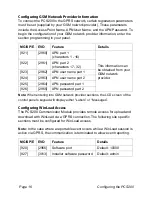
Page 16: ...Load Access The PCS200 Communicator Module provides remote access for upload and download with WinLoad via a GPRS connection The following site specific sections must be configured for WinLoad access...

Page 17: ...GPRS reporting Control panels with a PCS200 can also report system events to a monitoring station s IPR512 GPRS IP Monitoring Receiver MG SP E EVO Details 805 2950 1 Off 2 Off Landline only default 1...

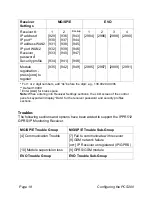
Page 18: ...tion press ARM to register 935 942 949 2985 2987 2989 2991 For 1 or 2 digit numbers add 0s before the digit e g 138 002 043 006 Default 10000 Enter MEM for blank space Note When entering into Receiver...

Page 19: ...he PCS200 9 Communication Trouble 5 Fail to communicate with receiver 1 6 Fail to communicate with receiver 2 7 Fail to communicate with receiver 3 8 Fail to communicate with receiver 4 9 IP Receiver...

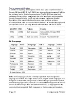
Page 20: ...If an unsupported language is selected messages will be sent in English Some languages like Hungarian or Romanian will generate 2 SMS messages per event reported and other languages will use special...

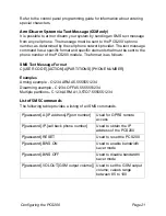
Page 21: ...t is as follows SMS Text Message Format C USER CODE ACTION A PARTITIONS PHONE NUMBER Examples Arming example C1234 ARM A5 5555551234 Disarming example C1234 OFF A5 5555551234 Multiple partitions C1234...

Page 22: ...ia text message you must use a cellular phone and enter P TCP IP password IP phone number to answer back i e Padmin IP 5551231234 The PCS200 will send a response to the specified phone number displayi...

Page 23: ...connect the In Field Upgrade connector to a PC with WinLoad To Upgrade Firmware 1 Launch WinLoad 2 Log on to WinLoad by entering your User and Password information 3 Click the In Field Firmware Progra...

Page 24: ...he presence of the GSM cell phone network approximately every 20 seconds If the connection is lost the panel can generate an alarm or trouble after the delay has elapsed programmed in section 2952 or...

Page 25: ...titions are enabled for that SMS number by enabling options 1 to 8 Press ENTER to go to the next screen 6 To select which events generate an SMS message enable or disable options 1 to 4 7 To save pres...

Page 26: ...ne which IP port to enter in the WinLoad or NEware GPRS connection settings This is the port that the module will listen for incoming GPRS communication This port is programmed in section 2966 with Di...

Page 27: ...PCS200 User PC Software Password If you press again the Exit Message will be displayed Viewing GSM IP Information with MG SP E Series 1 Press the key 2 Enter MASTER CODE 3 To enter SMS Setup press ARM...

Page 28: ...mation Alarm cancelled 1 2 3 4 Alarm cancelled with remote 1 2 3 4 Alarm cancelled through Internet 1 2 3 4 Alarm cancelled through End User PC Software 1 2 3 4 Alarm cancelled through Voice Module Ph...

Page 29: ...h 1 2 3 5 Arming through Installer PC software 1 2 3 One touch arming 1 2 3 Auto arming 1 2 3 Disarming 1 2 3 4 Disarming with remote 1 2 3 4 Disarming through internet 1 2 3 4 Disarming through end u...

Page 30: ...s wireless communication 1 2 Tamper trouble on module 1 2 4 6 Phone line trouble on module 1 2 4 6 Central station communication from module failed 1 2 4 6 Printer module trouble 1 2 4 6 AC power fail...

Page 31: ...n module 1 2 4 6 Phone line restored on module 1 2 4 6 Central station communication from module restored 1 2 4 6 Printer module restored 1 2 4 6 AC power restored on bus or wireless module 1 2 4 6 Ba...

Page 32: ...e 12 Digiplex EVO 24 Digiplex EVO 26 Dimensions 9 E E55 6 E65 6 Encryption 9 End user SMS programming 24 Error LED 23 Event Call Options 25 EVO192 6 EVO48 6 G GPRS 8 GPRS network 16 GPRS reporting 17...

Page 33: ...options 15 Registration parameters 16 Remote Firmware Upgrade 22 Required Optional Items 6 Reset 20 S Serial cable 11 Serial cable connector 11 Signal Strength 8 20 SIM Card Connection 10 SIM Card Er...

Page 34: ...uble Restore Messages 30 Troubles 18 TX 8 20 U Upgrading the Firmware 22 Upload download 21 User PC Software Password 25 V VDMP3 11 VDMP3 Connection 11 View GSM IP Information 25 Volume 12 W Wait for...

Page 35: ...________________________________________ _____________________________________________________________ _____________________________________________________________ ___________________________________...

Page 36: ...______ _____________________________________________________________ _____________________________________________________________ _____________________________________________________________ _______...

Page 37: ......

Page 38: ...ort in Canada or the U S call 1 800 791 1919 Monday to Friday from 8 00 a m to 8 00 p m EST For technical support outside Canada and the U S call 00 1 450 491 7444 Monday to Friday from 8 00 a m to 8...

Reviews: