background image

10 Reference & Installation Manual

2.8 S

YSTEM

R

ESET

Performing a system reset will set the Parakey to
default settings. Please note that if connected to a
control panel, the reset sequence of the Parakey
will not cause the control panel to reset and vice
versa. To execute a system reset perform the
following:

1) Remove the power connections ("+12" &

"

GND

") from the receiver.

2) Press and hold the [

PROG

] button and re-

connect the power connections to the receiver.

3) Wait approximately 2 seconds and release the

[

PROG

] button. The red LED will flash for 15

seconds, the keypad will beep, and all system
settings will be reset to factory default.

Summary of Contents for PRK-315

Page 1: ...Arm Disarm Wireless Module 433MHz V1 3 PRK 315 WITH KEELOQ HIGH SECURITY CODE ENCRYPTION Reference Installation Manual...

Page 2: ......

Page 3: ...nnas 6 Programmable Outputs PGMs 6 Hand Held Remote Control 7 Remote Control Button Identification 8 System Reset 10 HOW TO PROGRAM 13 SYSTEM PROGRAMMING 16 Access Code Length 16 Installer Code Defaul...

Page 4: ......

Page 5: ...to a specific user and therefore identifies the user to the control panel when used If desired it can be used as a stand alone system where the remote controls will only activate the on board PGM out...

Page 6: ...rectly to the Parakey Receiving Module Programmable Installer Code Software reset 1 2 TECHNICAL SPECIFICATIONS 1 2 1 Receiver Compatible Programming Keypads 616 V4 2A up 626 V4 1A up 636 DC input 12VD...

Page 7: ...trol panel When selecting an installation site please take into consideration that the maximum reception distance of the receiver is approximately 54 meters 175 feet line of sight The circuit is stati...

Page 8: ...least 2 inches around the panel box to permit adequate ventilation heat dissipation Selecting a site that is not susceptible to drastic changes in temperature and humidity 2 2 POWER COMMUNICATION 2 2...

Page 9: ...used as a stand alone system you will need a Paradox 12VDC Power Supply and a 12VDC backup battery Connect the power supply and the backup battery as shown in Figure 5 page 12 2 3 KEYPAD The Parakey R...

Page 10: ...ecommended for best results Do not cut bend or alter the antennas in any way as this may reduce the receiver s sensitivity range 2 5 PROGRAMMABLE OUTPUTS PGMS The Parakey provides four programmable ou...

Page 11: ...emote Controls OMN RCT1 Each button on a remote control can perform different actions depending on how the system is programmed These remote controls can transmit a signal up to a maximum of 95 meters...

Page 12: ...Reference Installation Manual 2 page 8 Figure 2 Changing the Batteries 2 7 REMOTE CONTROL BUTTON IDENTIFICATION Figure 3 on page 9 displays the 4 button RF transmitter and how the buttons are numbere...

Page 13: ...Parakey 9 Figure 3 Remote Control Button Identification...

Page 14: ...use the control panel to reset and vice versa To execute a system reset perform the following 1 Remove the power connections 12 GND from the receiver 2 Press and hold the PROG button and re connect th...

Page 15: ...Parakey 11 Figure 4 Connection with Control Panel...

Page 16: ...12 Reference Installation Manual Figure 5 Stand Alone Connection...

Page 17: ...ceiver flashes on and off at 2 second intervals To enter the Programming Mode press the PROG button located on the Parakey Receiver The program keypad will beep once the red LED will flash and the key...

Page 18: ...o 9 to enter the desired access code When the required data is entered the keypad will emit a confirmation beep and the Parakey will automatically save and exit the section If you make a mistake press...

Page 19: ...ting and press ENTER Sections 17 17 17 17 to 24 24 24 24 31 31 31 31 to 35 35 35 35 Feature Select After entering the section each key from 1 to 8 represents a feature or option The on off status of t...

Page 20: ...gth as set in the control panel at address 088 key 9 4 2 INSTALLER CODE DEFAULT 757575 Section 00 00 00 00 Access Code Programming The Installer Code allows you to program all the functions features o...

Page 21: ...Parakey 17 and each user must be defined with all three of these parameters User Access Code Remote Control Assignment User Remote Control Options Figure 6 Programming User Parameters...

Page 22: ...med PGMs will be activated The User Access Codes can be 4 or 6 digits in length see section 4 1 on page 16 with each digit being any value from 0 to 9 Program the User Access Code into the section cor...

Page 23: ...tem must be assigned to a user After entering the section corresponding to the desired user see Figure 6 on page 17 press the ENTER key and the READY and ARM lights will illuminate Then press button 1...

Page 24: ...24 correspond to users 1 through 8 respectively By turning keys 1 to 8 on or off set the desired remote control options as described on the next page and press ENTER When the following keys are enable...

Page 25: ...25 25 25 decimal select 0 0 0 0 to 4 4 4 4 When a remote control activated panic alarm is generated see section 4 3 3 on page 20 the Parakey can activate one of the four on board PGM outputs In sectio...

Page 26: ...ssor from disarming the system in case of a panic situation In section 26 select only one Section 26 Key 0 ON No output on panic alarm Key 1 ON Toggle output 1 on panic alarm Key 2 ON Toggle output 2...

Page 27: ...n or for a specified period of time Each PGM output can be programmed with a separate output timer In the section corresponding to the desired PGM output where sections 27 to 30 represent PGM outputs...

Page 28: ...al feature For example if button 1 is programmed to toggle PGM outputs 1 and 2 then button 1 on all the remote controls will toggle PGM outputs 1 and 2 In the section corresponding to the desired butt...

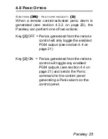
Page 29: ...rakey can perform one of two actions Key 2 OFF Panics generated from the remote control will only toggle the enabled PGM output see section 4 4 on page 21 Key 2 ON Panics generated from the remote con...

Page 30: ...s warranty is expressly limited to repairing or replacing at Seller s option any product not meeting the specifications In no event shall the Seller be liable to the buyer or any other person for any...

Page 31: ......

Page 32: ......

Reviews: