Installation
2-2
3166-A2-GB20-20
March 1999
Installation
Procedure
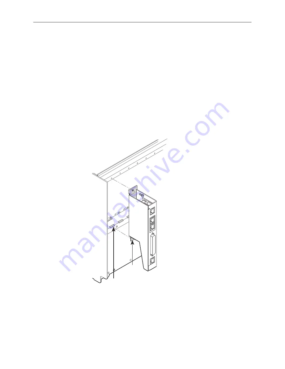
To install the DSU and rear connector module:
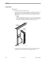
1. At the rear of the carrier, set the tab on the rear connector module into one of
the slotted grooves on the carrier’s backplane. Loosely fasten the screws.
Make sure the rear connector module uses the same slot position intended
for the DSU.
NOTE:
If an auxiliary backplane for Models 3151 or 3161 DSUs is installed in the
same carrier, verify that it is mounted over Slots 9–16. Slot 9 is rendered
inaccessible if the auxiliary backplane is mounted over Slots 1–8.
98-16083
3000 Series
Carrier
Slots
Tabs
Rear
Connector
Module
2. Loosely fasten the screw attached to the rear connector plate, allowing for
slight adjustment that may be needed when installing the DSU.
Summary of Contents for 3166 DSU
Page 1: ...ACCULINK 3166 DSU CSU USER S GUIDE Document No 3166 A2 GB20 20 March 1999...
Page 16: ...About This Guide x 3166 A2 GB20 20 March 1999 This page intentionally left blank...
Page 20: ...Introduction 1 4 3166 A2 GB20 20 March 1999 This page intentionally left blank...
Page 68: ...SDCP Operation 3 42 3166 A2 GB20 20 March 1999 This page intentionally left blank...
Page 102: ...SDCP Menu A 2 3166 A2 GB20 20 March 1999 This page intentionally left blank...
Page 140: ...Pin Assignments D 12 3166 A2 GB20 20 March 1999 This page intentionally left blank...
Page 166: ...SNMP MIB Objects E 26 3166 A2 GB20 20 March 1999 This page intentionally left blank...
Page 192: ...Equipment List I 2 3166 A2 GB20 20 March 1999 This page intentionally left blank...

