3
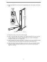
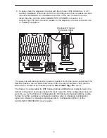
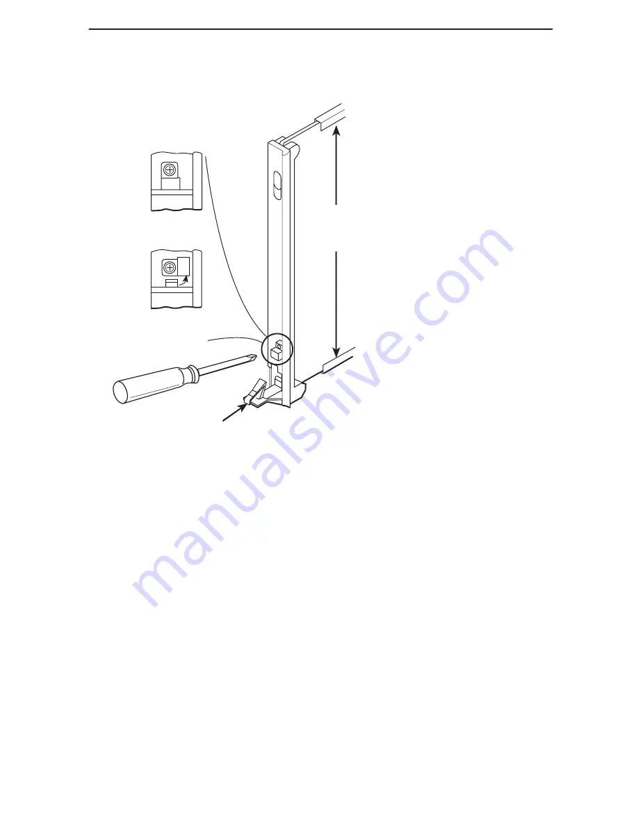
2. Insert the DSU/CSU circuit card into the appropriate slot in the carrier and lock the
latch.
Circuit
Card
Guides
Circuit
Pack
Lock
Latch
Open
(Unlocked)
Closed
(Locked)
495-14813
3. Tighten the screw on the rear connector module.
4. Attach a modular cable (not included) to the COM connector of the rear connector
module. (See the
User’s Guide for detailed cable and connector information.)
Connect the other end to a terminal or PC.
5. Attach the DB25 port cable to the PORT 1 connector on the rear connector module.
Connect the other end of the cable to the customer premises equipment.
6. Attach the network cable to the Network connector on the rear connector module.
Connect the other end of the network cable to the connection provided by the
telephone company.


