background image

 4

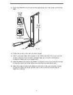
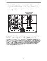
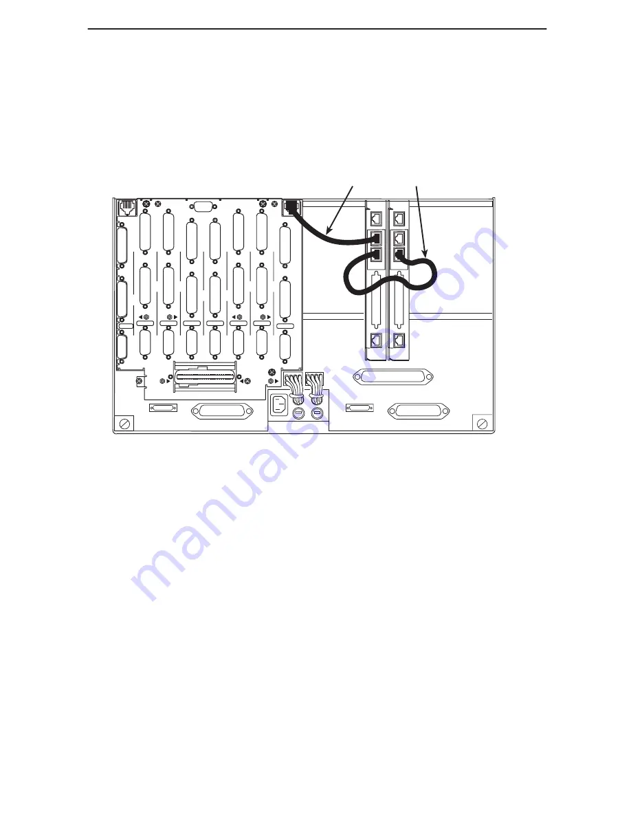
7. To daisy-chain the diagnostic channel with that of other 3166 DSU/CSUs or a T1

auxiliary backplane, insert one end of the short diagnostic channel extension cable
into either DIAGNOSTIC CHANNEL connector on the rear connector module.
Insert the other end into either DIAGNOSTIC CHANNEL connector of a
neighboring 3166 rear connector module, or the diagnostic channel connector of a
T1 auxiliary backplane.

98-16080

PORT

1

PORT

1

PORT

1

PORT

1

PORT

1

PORT

1

PORT

1

PORT

1

CLOCK IN

DIAGNOSTIC

CHAN

PORT

2

PORT

2

PORT

2

PORT

2

PORT

2

PORT

2

PORT

2

PORT

2

DTE

DTE

DTE

DTE

DTE

DTE

DTE

DTE

SLT 8 (16)

SLOT 6 (14)

SLOT 7 (15)

SLOT 5 (13)

SLOT 4 (12)

SLOT 3 (11)

SLOT 2 (10)

SLOT 1 (9)

T1 NETWORK

INTERFACE

COMCODE

107170409

MODEL NO.
3100-F1-900

DIAGNOSTIC

CHAN

CAUTION:

DISCONNECT ALL TELEPHONE LINES AT THE NETWORK
INTERFACE BEFORE TOUCHING OR SERVICING

Diagnostic Channel

Extension Cable

NET

PORT 1

COM

DIAGNOSTIC

CHANNEL

NET

PORT 1

COM

DIAGNOSTIC

CHANNEL

The power-up self-test begins when power is applied. During the power-up self-test, the
Fail LED flashes, then all LEDs blink twice. When the test is complete, verify that the
DSU/CSU is functional by observing that the OK and NET Sig LEDs are lit.

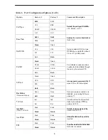
The Factory 1 configuration for ESF framing format and B8ZS line coding format is the
default configuration and is appropriate for most networks. If this configuration does not
work for you, try the Factory 2 configuration for D4 framing format and AMI line coding
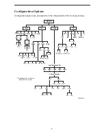
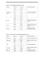
format. To further customize configuration options, refer to 

Changing Configuration

Options in Chapter 3, Operation, and Appendix C, Configuration Options, in the
ACCULINK 3166 DSU/CSU User’s Guide.

Summary of Contents for 3166 DSU

Page 1: ...ACCULINK 3166 DSU CSU QUICK REFERENCE Document No 3166 A2 GL11 10...

Page 2: ...and issued as a new release to this manual Warranty Sales and Service Information Contact your local sales representative service representative or distributor directly for any help needed For additio...

Page 3: ...w paradyne com Select Service Support Technical Manuals T1 E1 Digital Access Devices Select the following document 3166 A2 GB20 ACCULINK 3166 DSU CSU User s Guide To request a paper copy of a Paradyne...

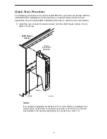
Page 4: ...U CSU User s Guide for more information 1 Install the rear connector module loosely onto the 3000 Series Carrier Do not tighten the screw 98 16083 3000 Series Carrier Slots Tabs Rear Connector Module...

Page 5: ...connector of the rear connector module See the User s Guide for detailed cable and connector information Connect the other end to a terminal or PC 5 Attach the DB25 port cable to the PORT 1 connector...

Page 6: ...F1 900 DIAGNOSTIC CHAN CAUTION DISCONNECT ALLTELEPHONE LINES AT THE NETWORK INTERFACE BEFORE TOUCHING OR SERVICING Diagnostic Channel Extension Cable NET PORT 1 COM DIAGNOSTIC CHANNEL NET PORT 1 COM D...

Page 7: ...pbk Ptrns Lamp QRSS 511 Abort Mon LLBUP LLBDN 54UP 54DN FT1UP FT1DN PLB RLB LLB Abort DCLB DTLB QRSS1in8 511 Send Cnfig Ctrl Rel ClrReg Reset CID Passwd ACO DL Call Load Edit Area From Choose Function...

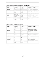
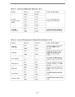
Page 8: ...hrough the port by the external DTE Both Both y Disab Disab All Ones DTR DTR All ones sent to network DTE T1 All Ones RTS RTS All ones sent to network DTE T1 when DTR or RTS interrupted Both Both Rcv...

Page 9: ...nab Enab Specifies whether the EDL Mgmt Link Disab Disab S ecifies whether the EDL Management Link is enabled Table 2 Network Interface Configuration Options 1 of 2 Option Factory 1 Factory 2 Comments...

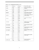
Page 10: ...and FCC g is B8ZS Disab 62411 ANSI T1 403 and FCC Part 68 Technical Publication Circuit Ident Edit Edit Specifies the transmission vendor s Circuit Ident Clear Clear S ecifies the transmission vendor...

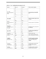
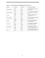
Page 11: ...ASCII Controls how the COM port is used Term Term used Disab Disab ComExtDev AT AT Specifies the type of external commands allowed Other Other commands allowed ComConnPrefix Edit Edit Controls the COM...

Page 12: ...its 2 2 the COM port Ignore DTR Yes Yes Specifies whether the COM port Ignore DTR No No S ecifies whether the COM ort ignores DTR CmInActTm COM P t I ti it Enab Enab Specifies whether the i ti t di t...

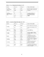
Page 13: ...alarm messages Alrm Msg Com Com Sends alarm messages to COM port SNMP Trap Enab Enab Sends SNMP traps SNMP Trap Disab Disab Sends SNMP traps TrapDisc Enab Enab Specifies whether the modem ti ill di t...

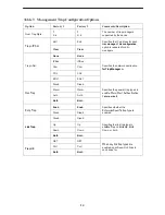
Page 14: ...onds to SNMP session requests NMS Valid Enab Enab Specifies whether the DSU CSU validates the IP address of an NMS Valid Disab Disab validates the IP address of an SNMP manager attempting access Num S...

Page 15: ...ity name 1 Comm nit Name2 Edit Edit A community name that is allowed CommunityName2 Clear Clear A community name that is allowed access to this device Access 2 Read Read The type of access allowed for...

Page 16: ...er n FDL FDL for Trap Manager n EDL1 EDL1 Disab Disab Gen Trap Warm Warm Specifies the general trap types to bl W St t A th ti ti Gen Trap Auth Auth enable WarmStart Authentication Failure or both Bot...

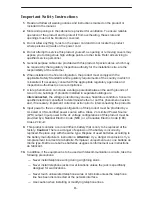
Page 17: ...e potential may cause a hazardous condition Consult a qualified electrical consultant to determine whether or not this phenomenon exists and if necessary implement corrective action prior to interconn...

Page 18: ...fications are expressly approved by Paradyne Corporation WARNING To Users of Digital Apparatus in Canada This Class A digital apparatus meets all requirements of the Canadian interference causing equi...

Page 19: ...If this happens the telephone company will provide advance notice in order for you to make the necessary modifications in order to maintain uninterrupted service 5 If you experience trouble with this...

Page 20: ...or alterations made by the user to this equipment or equipment malfunctions may give the telecommunications company cause to request to disconnect the equipment Users should ensure for their own prote...

Reviews: