3
3000-A2-GZ41-50
July 1999
4. Aligning the circuit card with the rear connector plate, slide the DSU into the
slot until the connectors seat firmly into the back of the carrier.
5. Press the faceplate latch to secure the DSU in the carrier, rotate the circuit
pack lock into the closed position, and tighten the screw.
6. Return to the rear of the carrier and tighten the rear connector plate screw.
7. At the rear of the carrier, connect the DTE to the rear connector plate (see
Figure 2):
— If you are using an EIA-232-D interface cable, connect the EIA-232-D
cable to the top DTE connector on the rear connector plate.
— If you are using a V.35 cable with a 34-pin connector, use the V.35
adapter as described in the next procedure.
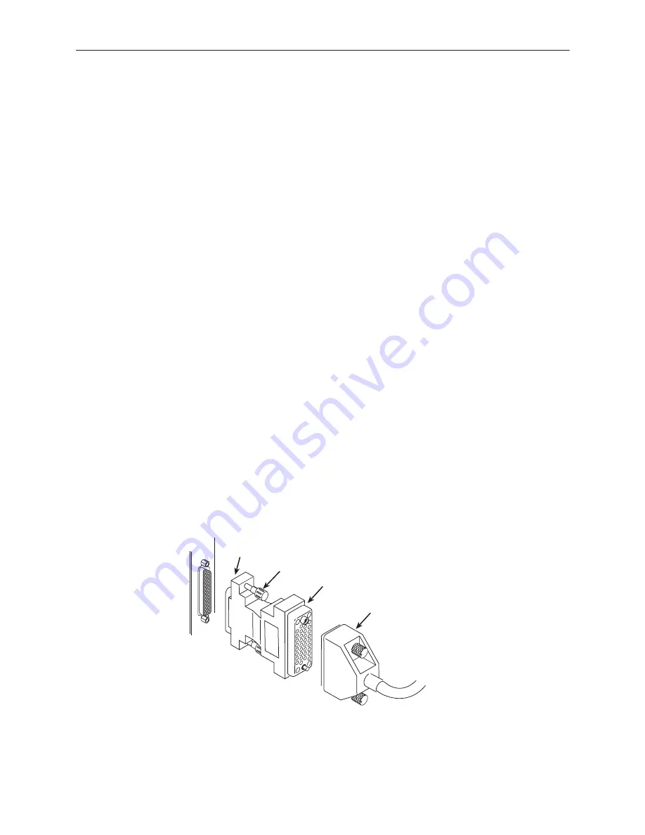
Connecting to a 34-Pin V.35 Interface
To connect the V.35 adapter:
Procedure
1. Connect the 25-pin end of the V.35 adapter to the bottom DTE connector on
the rear connector plate. Tighten the screws on both sides of the adapter.
2. Connect the DTE’s V.35 cable to the V.35 adapter. Tighten the screws on
both sides of the cable connector.
3. If a ferrite choke was supplied with your DSU, install it on the V.35 cable as
closely as possible to the adapter. Secure it in position, if necessary, with a
cable tie.
Table 1 lists the pin assignments for the rear connector plate and the V.35
adapter.
25-Pin Connector
V.35 Adapter
V.35 Cable
Thumbscrews
99-16298
Figure 3.
V.35 Adapter


