4. Configuration Options
9128-A2-GB20-80
September 2002
4-69
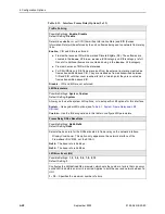
Source EDLCI
Possible Settings: 0 – 62
Default Setting: Initially blank; no default.
Specifies the source Embedded Data Link Connection Identifier (EDLCI) for a frame relay
interface when a multiplexed DLCI record is selected as one end of a connection.
Display Conditions – This option only appears when Source DLCI contains a
multiplexed DLCI record number.
0 – 62 – Specifies the EDLCI number.
Primary Destination Link
Possible Settings: Net1-FR1,
ISDN Link Name, Rtr-S0
Default Setting: Initially blank; no default.
Specifies the frame relay interface used as the primary destination link; the to end of a
from-to link. The only valid settings for this configuration option are frame relay interfaces
that have at least one DLCI or EDLCI defined which are not part of a PVC connection or
management link. For example, if the network interface has no DLCIs defined, Net1-FR1
would not appear as a valid setting.
Net1-FR1 – Specifies the Network interface as the destination link.
ISDN Link Name – For units with ISDN backup capability, specifies the ISDN link of the
DBM as the destination of the connection. This can be any nonnull link name configured
on an ISDN frame relay link.
Rtr-S0 – For the FrameSaver SLV 9126-II Router, specifies the virtual router port as the
destination link.
Primary Destination DLCI
Possible Settings: 16 – 1007
Default Setting: Initially blank; no default.
Specifies the primary destination DLCI for a frame relay interface. The DLCI must be
defined and cannot be part of a PVC connection or management link. For multiplexed
DLCIs, at least one EDLCI must be unconnected for the DLCI to be a valid selection.
NOTES:
– Primary Destination DLCI has no value if Primary Destination Link contains no
value.
– When an ISDN DBM is installed and the DLCI assigned to the PVC is in a Backup
Group (see
Table 4-14, DLCI Record Options
), the letter designation assigned to
the group of DLCIs appears next to the primary destination DLCI number on the
Management PVCs Options screen.
16 – 1007 – Specifies the DLCI number.
Table 4-15. PVC Connection Options (2 of 4)
Summary of Contents for 9126
Page 150: ...4 Configuration Options 4 106 September 2002 9128 A2 GB20 80 ...
Page 182: ...6 Security and Logins 6 16 September 2002 9128 A2 GB20 80 ...
Page 264: ...7 Operation and Maintenance 7 82 September 2002 9128 A2 GB20 80 ...
Page 348: ...A Menu Hierarchy A 4 September 2002 9128 A2 GB20 80 ...
Page 440: ...E Connectors Cables and Pin Assignments E 18 September 2002 9128 A2 GB20 80 ...

