Setting Up
5-66
9161-A2-GH30-40
April 1999
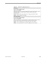
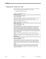
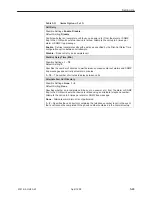
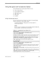
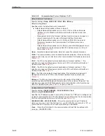
Table 5-13.
Alarm Options (3 of 3)
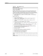
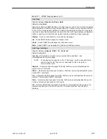
System Alarm Relay
Possible Settings: Enable, Disable
Default Setting: Disable
Specifies whether an alarm condition for the T1 access unit will activate the system
alarm relay. The alarm relay is deactivated when the condition causing the alarm is
corrected. If more than one alarm condition is present, the alarm relay remains active
until all alarm conditions are cleared for that T1 access unit. You can also deactivate an
alarm via the System Alarm Relay Cut-Off selection from the Control menu.
System Alarm Relay only appears if the NAM is installed in a 5-slot housing or
access carrier.
Alarm conditions are:
Power supply/fan tray alarm.
Continuous Loss of Signal (LOS) condition at either the Network or DSX-1
interface, or on any OCU-DP port.
Continuous Out of Frame (OOF) condition at either the Network or DSX-1
interface.
Yellow alarm on either the Network or DSX-1 interface.
Continuous Out of Frame (OOF) condition at any synchronous data port that has
the EDL set to Enable.
Alarm Indication Signal (AIS) received at either the Network or DSX-1 interface.
Excessive Error Rate (EER) detected at the Network interface.
Excessive Error Rate (EER) detected at any synchronous data port that has
Embedded Data Link set to Enable (see
Table 5-3
).
Primary or Secondary Clock Failure.
Failure of an APM.
An APM is inserted that does not match the configuration.
Abnormal Station Code on any OCU-DP port.
DDS Network Failure on any OCU-DP port.
Loss of Loop Timing on any OCU-DP port.
Enable – Activates alarm conditions on the system alarm relay when an alarm condition
occurs.
Disable – Does not activate alarm conditions on the system alarm relay when an alarm
condition occurs.
Summary of Contents for 9161 Single T1
Page 1: ...MODEL 916x 926x T1 ACCESS MUX TECHNICAL REFERENCE Document No 9161 A2 GH30 40 April 1999...
Page 34: ...Management and Control 2 6 9161 A2 GH30 40 April 1999 This page intentionally left blank...
Page 54: ...User Interface 4 10 9161 A2 GH30 40 April 1999 This page intentionally left blank...
Page 92: ...Setting Up 5 38 9161 A2 GH30 40 April 1999 Example Channel Allocation...
Page 142: ...Security 6 10 9161 A2 GH30 40 April 1999 This page intentionally left blank...
Page 252: ...IP Addressing B 8 9161 A2 GH30 40 April 1999 This page intentionally left blank...

