Setting Up
5-18
9161-A2-GH30-40
April 1999
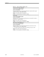
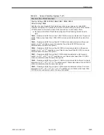
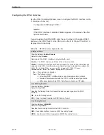
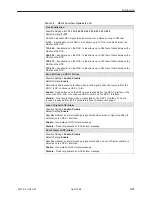
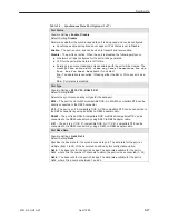
Table 5-3.
Synchronous Data Port Options (2 of 7)
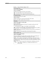
Transmit Clock Source
Possible Settings: Internal, External
Default Setting: Internal
Determines whether the transmitted data is clocked by the synchronous data port
internal clock, or by the clock supplied by the DTE connected to the synchronous data
port.
Internal – The DCE clocks transmitted data, and uses the interchange circuit DB
(CCITT 114) – Transmit Signal Element Timing (TXC) (DCE source) for timing the
incoming transmitted data.
External – The DTE externally provides the clock for the transmitted data, and the
synchronous data port uses the interchange circuit DA (CCITT 113) – Transmit Signal
Element Timing (XTXC) (DTE source) for timing the incoming transmitted data.
NOTE:
When external clock is used, it must be synchronized to the same clock
source as the system.
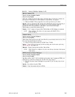
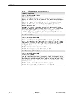
Invert Transmit Clock
Possible Settings: Enable, Disable
Default Setting: Disable
Determines whether the clock supplied by the DCE on interchange circuit DB
(CCITT 114) – Transmit Signal Element Timing (DCE Source) TXC is phase inverted
with respect to interchange circuit BA (CCITT 103) – Transmitted Data (TD). Use this
configuration option when long cable lengths between the NAM and the DTE are
causing data errors.
Enable – Phase inverts the TXC clock on the DCE.
Disable – Does not phase invert the TXC clock on the DCE.
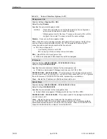
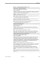
Invert Transmit and Received Data
Possible Settings: Enable, Disable
Default Setting: Disable
Specifies whether the transmitted and received data for the synchronous data port is
logically inverted before being transmitted or after being received from the network. Use
this configuration option for applications where data is being transported using HDLC
protocol, whereby inverting the data ensures that the ones density requirements for the
network are met.
Enable – Inverts the transmitted and received data for the port.
Disable – Does not invert the transmitted and received data for the port.
Summary of Contents for 9161 Single T1
Page 1: ...MODEL 916x 926x T1 ACCESS MUX TECHNICAL REFERENCE Document No 9161 A2 GH30 40 April 1999...
Page 34: ...Management and Control 2 6 9161 A2 GH30 40 April 1999 This page intentionally left blank...
Page 54: ...User Interface 4 10 9161 A2 GH30 40 April 1999 This page intentionally left blank...
Page 92: ...Setting Up 5 38 9161 A2 GH30 40 April 1999 Example Channel Allocation...
Page 142: ...Security 6 10 9161 A2 GH30 40 April 1999 This page intentionally left blank...
Page 252: ...IP Addressing B 8 9161 A2 GH30 40 April 1999 This page intentionally left blank...

