background image

 2

Package Checklist

Verify that your package contains the following:

-

T1 NAM and associated I/O card

-

Network Interface Cable (14 ft.)

-

DB9 COM Port Cable (14 ft.)

-

Affidavit Requirements for Connection to Digital Service

Be sure to register your warranty at www.paradyne.com/warranty.

Available Options

The following options are separately orderable:

-

RJ48C modular cable for network access (20 ft.)

-

RJ48H T1 mass termination cable (5 ft.) for connecting seven T1 NAMs to an
M66 block

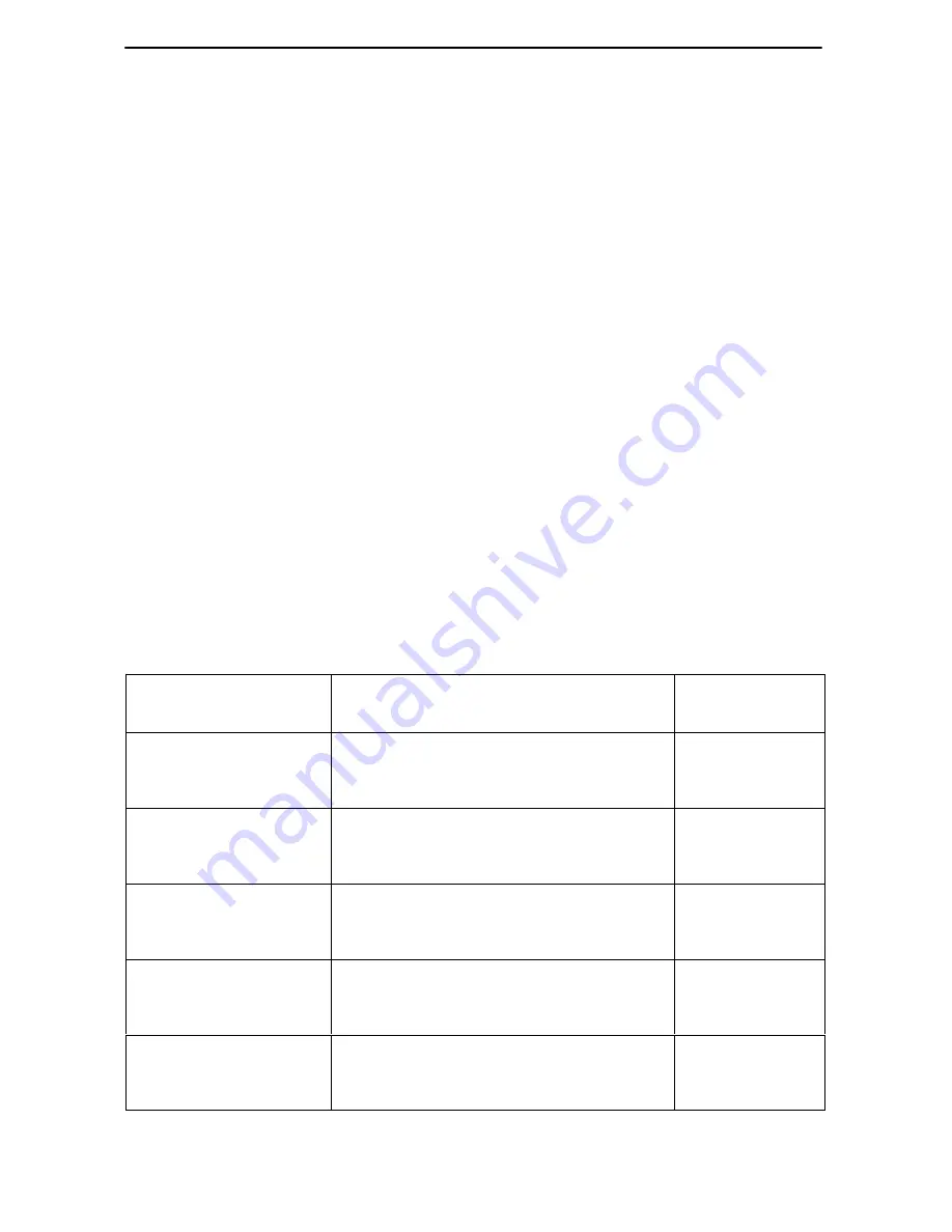
Cables You May Need to Order

The following cables and connectors are specifically for this product.

If connecting to a . . .

You need a . . .

Feature
Number

Terminal/printer (DB25
interface/connector –
EIA-232 connection)

COM Port-to-Terminal/Printer cable
(14 ft.)

3100-F2-540

PC (DB9
interface/connector –
EIA-232 connection)

COM Port-to-PC cable (14 ft.)

3100-F2-550

DTE with a V.35
interface/connector

V.35 Interconnect cable (1 ft.)
MS34 to DB25 adapter cable for 
each port: Port 1 and/or Port 2

3100-F1-570

DTE with a V.11/X.21
interface/connector

V.11/X.21 Interconnect cable (1 ft.)
DB15 to DB25 adapter cable for each
port: Port 1 and/or Port 2

3100-F1-571

DTE with a RS-449
interface/connector

RS499 Interconnect cable (1 ft.)
DB37 to DB25 DTE adapter cable for
each port: Port 1 and/or Port 2

3100-F1-580

Summary of Contents for 9261

Page 1: ...om Select Library Technical Manuals NextEDGE Multiservices Access System Documents Select the following document 9161 A2 GH30 Model 916x 926x T1 Access Mux Technical Reference To order a paper copy of...

Page 2: ...onnectors are specifically for this product If connecting to a You need a Feature Number Terminal printer DB25 interface connector EIA 232 connection COM Port to Terminal Printer cable 14 ft 3100 F2 5...

Page 3: ...No 9000 A2 GN16 5 Slot Housing with DC Power Supply Installation Instructions Document No 9000 A2 GN1C 9000 Series Access Carrier with AC Power Supply Installation Instructions Document No 9000 A2 GN...

Page 4: ...facilitate correct installation 1 Remove the I O card from the shipping box Handle only by the top and bottom edges to avoid damaging the card 2 At the rear of the housing align the I O card with the...

Page 5: ...sert the other end of the cable into the RJ48C modular jack Connecting to a DTE If the DTE cable type is V 35 RS449 or V 11 X 21 separately orderable 1 Connect the plug to the V 35 RS449 or V 11 X 21...

Page 6: ...ard to display the Main Menu If you need to configure for other than a direct link see the Technical Reference Set the speed of the async VT100 compatible terminal so it matches the NAM s factory load...

Page 7: ...the housing s bezel if applicable See the housing installation instructions for information 2 Remove the NAM from the shipping box Handle only by the top and bottom edges to avoid damaging the card 3...

Page 8: ...e upper and lower ejector latches on the housing to lock in place then tighten the captive screws 7 Replace the housing s bezel if applicable Removing Replacing the I O Card 1 Remove the NAM from the...

Page 9: ...Troubleshooting and Maintenance in the Technical Reference for information on the test jacks General Status LEDs Label Indication Color What It Means OK Power and Operational Status Green ON NAM has...

Page 10: ...ent on the Network 1 Network 2 interface Current alarm conditions H Loss of Signal LOS H Loss of Frame LOF H Excessive Error Rate EER H Yellow Alarm H Alarm Indication Signal AIS OFF No alarm conditio...

Page 11: ...vice representative Power Up Self Test fails Only Alarm LED is on after power up The NAM has detected an internal hardware failure 1 Reset the NAM and try again see the Technical Reference 2 Contact y...

Page 12: ...ny representative Within the U S A call 1 800 870 2221 Outside the U S A call 1 727 530 2340 Document Feedback We welcome your comments and suggestions about this document Please mail them to Technica...

Reviews: