2. Cabling
4821-A2-GN20-00
April 2002
2-7
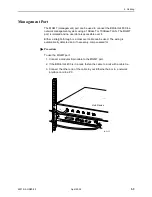
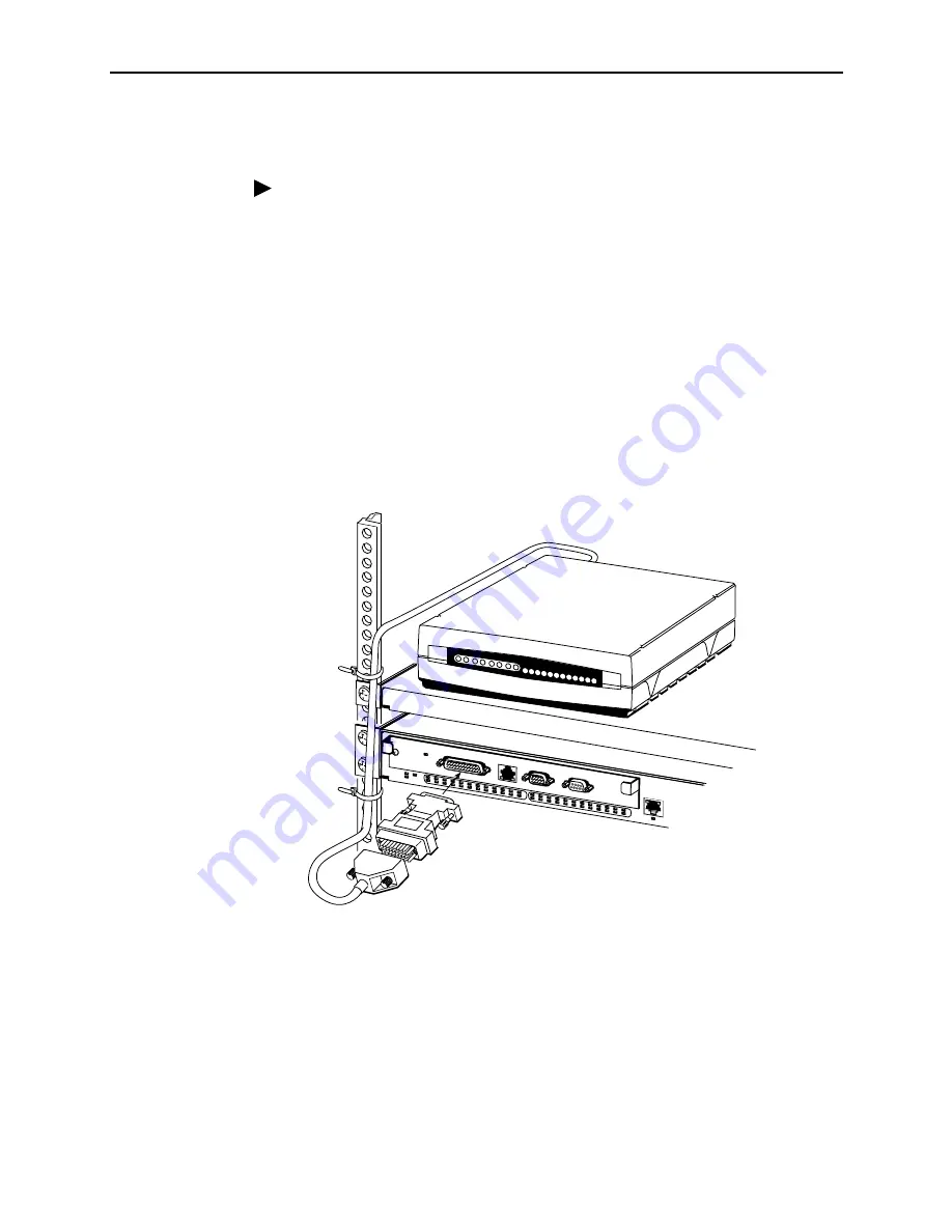
V.35/X.21 Connector (4804 Management Module)
Procedure
To connect to a CSU or router:
1. Determine the electrical interface required: V.35, EIA-530-A, or X.21.
2. Connect the appropriate adapter or adapter cable to the V.35/X.21 connector
of the 4804 Management Module.
3. Fasten the connector to the Management Module with its captive screws.
4. If you are using a short adapter and a separate cable, connect a cable to the
adapter and fasten the two together with screws or cable ties.
5. If the BitStorm 4800 is in a rack, dress the cable to the left side of the rack, and
fasten it to the rail with cable ties.
6. Connect the other end of the cable to the CSU or router. Fasten the connector
to the CSU or router with its captive screws or a cable tie.
The default interface for the BitStorm 4800 software is V.35. If you use a V.35
interface you do not need to configure the software to accommodate it. For an
EIA-530-A or X.21 interface, see
02-17078
OK
ALARM
TEST
1
2
4
6
8
10
12
14
16
18
20
22
24
26
28
30
32
34
36
38
40
42
44
46
48
47
MGMT
CONSOLE
MODEM
ALARM
V.35/X.21
3
5
7
11
13
15
17
19
9
21
23
25
27
29
31
33
35
37
39
41
43
45
4804
Router

