background image

 3

3000-A2-GZ41-60

December 1999

4. Aligning the circuit card with the rear connector plate, slide the DSU into the

slot until the connectors seat firmly into the back of the carrier.

5. Press the faceplate latch to secure the DSU in the carrier, rotate the circuit

pack lock into the closed position, and tighten the screw.

6. Return to the rear of the carrier and tighten the rear connector plate screw.

7. At the rear of the carrier, connect the DTE to the rear connector plate 

(see Figure 2):

— If you are using an EIA-232-D interface cable, connect the EIA-232-D

cable to the top DTE connector on the rear connector plate.

— If you are using a V.35 cable with a 34-pin connector, use the V.35

adapter as described in the next procedure.

Connecting to a 34-Pin V.35 Interface

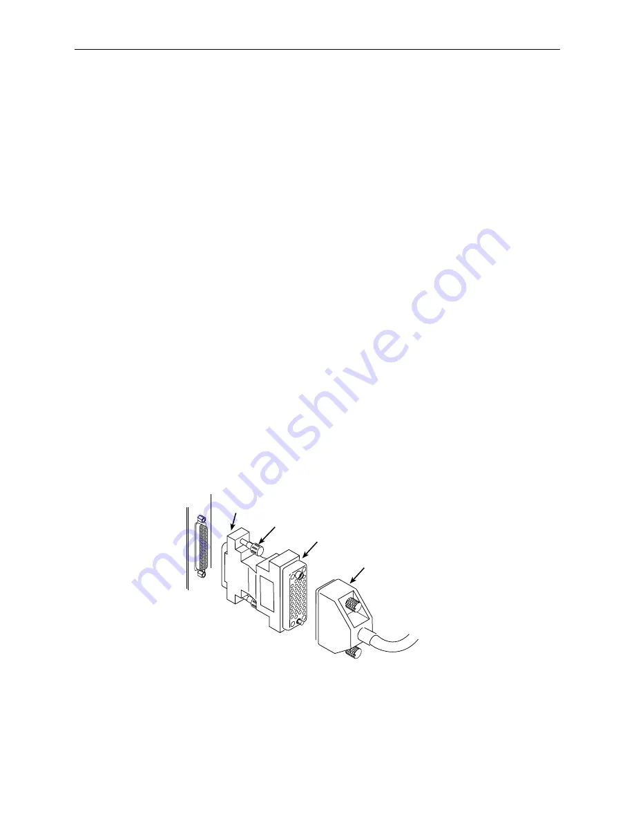
To connect the V.35 adapter plug or V.35 adapter cable:

"

Procedure

1. Connect the 25-pin end of the V.35 adapter plug or cable to the bottom DTE

connector on the rear connector plate. Tighten the screws on both sides of
the adapter.

2. Connect the DTE’s V.35 cable to the V.35 adapter plug or cable. Tighten the

screws on both sides of the cable connector.

3. If a ferrite choke was supplied with your DSU, install it on the adapter cable if

present, or on the V.35 cable as close as possible to the adapter plug.
Secure the ferrite choke in position, if necessary, with a cable tie.

25-Pin Connector

V.35 Adapter

V.35 Cable

Thumbscrews

99-16298

Figure 3.

V.35 Adapter Plug Installation

Summary of Contents for Compshere 3000 Series

Page 1: ...dge of its circuit card Figure 1 When the rear connector plate is installed in a COMSPHERE 3000 Series Carrier you can remove the modular DSU or 3800 Series modem without disturbing the DTE cables attached to the rear connector plate at the back of the carrier The rear connector plate has two 25 pin DTE connectors One is a an EIA 232 D V 24 connector and the other is an ITU T V 35 connector If you...

Page 2: ...tative To install a DSU and its rear connector plate for the first time Procedure 1 At the rear of the carrier set the tab on the rear connector plate into one of the slots on the carrier s backplane Figure 2 Make sure the rear connector plate uses the same slot position intended for the DSU 2 Loosely fasten the screw attached to the rear connector plate allowing for slight adjustment that may be ...

Page 3: ...ou are using a V 35 cable with a 34 pin connector use the V 35 adapter as described in the next procedure Connecting to a 34 Pin V 35 Interface To connect the V 35 adapter plug or V 35 adapter cable Procedure 1 Connect the 25 pin end of the V 35 adapter plug or cable to the bottom DTE connector on the rear connector plate Tighten the screws on both sides of the adapter 2 Connect the DTE s V 35 cab...

Page 4: ...mation Contact your local sales representative service representative or distributor directly for any help needed For additional information concerning warranty sales service repair installation documentation training distributor locations or Paradyne worldwide office locations use one of the following methods H Internet Visit the Paradyne World Wide Web site at www paradyne com Be sure to registe...

Reviews: