background image

 Glossary

Glossary-5

3821-A2-GB20-40

January 1999

handshaking

The exchange of predetermined codes and signals (tones) to establish a connection
between two modems.

HDLC

High-level Data Link Control. A communications protocol defined by ISO.

host

A computer attached to a network that shares its information and devices with the rest of
the network.

Hz

A unit of frequency (hertz) that equals one cycle per second.

ISO

International Organization for Standardization.

ITU-T

The Telecommunications Standardization Sector of the International
Telecommunications Union, an advisory committee established by the United Nations to
recommend communications standards and policies. Before March 1993 it was called
CCITT.

JM8

A jack used for leased-line networks. Pins 1 and 2 are the transmit pair and Pins 7 and 8
are the receive pair.

LCD

Liquid Crystal Display. The device that permits text to be displayed on the DCP or
SDCP.

leased line

A private line connection exclusively for the user. No dialing is necessary.

LED

Light-Emitting Diode. A light or status indicator on the DCP or SDCP that glows in
response to the presence of a certain condition (e.g., Alrm).

local analog loopback

Test in which the modem’s transmit VF signal is looped to its receiver.

long space disconnect

A disconnect can occur if the modem receives an extended space from a remote modem;
for example, when a remote modem is commanded to disconnect, it transmits a
continuous space to the modem before disconnecting.

loopback test

Any test that verifies a device’s integrity by connecting the device’s output of one
direction to the device’s input of the other direction, then checking the received signal
for errors.

LSD

Line Signal Detect. A signal between the DTE and modem indicating energy exists on
the transmission circuit.

MNP

This protocol (Microcom Networking Protocol) detects and corrects data errors caused
by telephone line noise and signal distortion. MNP5 includes data compression.

modem

MOdulator/DEModulator. A device that transforms signals from digital to analog form
and vice versa.

modulation

The process of varying some characteristics (usually amplitude, frequency, and/or phase)
of a carrier wave to form data transmissions.

off-hook

The state of a telephone or modem that is being used.

on-hook

The state of a telephone or modem that is not being used.

Summary of Contents for COMSPHERE 3821PLUS

Page 1: ...COMSPHERE 3821PLUS MODEM USER S GUIDE Document No 3821 A2 GB20 40 January 1999 ...

Page 2: ...site at http www paradyne com Via Telephone Call our automated call system to receive current information via fax or to speak with a company representative Within the U S A call 1 800 870 2221 Outside the U S A call 1 727 530 2340 Trademarks All products and services mentioned herein are the trademarks service marks registered trademarks or registered service marks of their respective owners COPYR...

Page 3: ... authority for the installation site are the responsibility of the customer 6 When installed in the final configuration the product must comply with the applicable Safety Standards and regulatory requirements of the country in which it is installed If necessary consult with the appropriate regulatory agencies and inspection authorities to ensure compliance In addition if the equipment is to be use...

Page 4: ...COMSPHERE 3821Plus Modem C January 1999 3821 A2 GB20 40 Notices ...

Page 5: ...or you to make the necessary modifications in order to maintain uninterrupted service 6 If you experience trouble with this equipment please contact your sales or service representative as appropriate for repair or warranty information If the product needs to be returned to the company service center for repair contact them directly for return instructions using one of the following methods Via th...

Page 6: ...ral areas The Load Number for this equipment is listed on a label on the modem The Load Number LN assigned to each terminal device denotes the percentage of the total load to be connected to a telephone loop which is used by the device to prevent overloading The termination on a loop may consist of any combination of devices subject only to the requirement that the total of the Load Numbers of all...

Page 7: ... continues to comply with the requirements of EN41003 for TNV Telephone Network Voltage circuits and EN60950 for SELV Safety Extra Low Voltage circuits after making connection between circuits Japan Notices This equipment is classified in the 1st Class category When used in a residential area or in an adjacent area thereto radio interference may be caused to radios and TV receivers etc VCCI 1 Rest...

Page 8: ...COMSPHERE 3821Plus Modem G January 1999 3821 A2 GB20 40 This page intentionally left blank ...

Page 9: ...1Plus Modem Installation Overview 2 1 3821Plus Installation 2 1 Install Communications Software 2 5 Select Factory Configuration Options 2 5 3 SDCP Menus Menu Structure 3 2 Modem Status Messages 3 3 Modem Select Branch 3 7 Quick Configuration Display 3 7 Call Setup Branch 3 9 Status Branch 3 11 Test Branch 3 13 Configure Branch 3 15 Control Branch 3 47 Automatic Firmware Download 3 49 Remote Branc...

Page 10: ... 26 Initialization Strings 4 27 5 Fax Operation Overview 5 1 Fax Operation 5 1 6 Remote Access Overview 6 1 Remote Access 6 1 7 Security Overview 7 1 Password Types 7 1 Originate Security 7 2 Answer Security 7 2 Callback Security 7 3 Security Branch 7 3 Security Configuration Options 7 9 A SDCP Menu Tree Overview A 1 B Result Codes Overview B 1 C Troubleshooting Overview C 1 Automatic Firmware Dow...

Page 11: ...Assignments E 3 F ITU T V 25bis Dialing Commands and Responses Overview F 1 Call Request Commands F 2 Call Response F 2 Call Answer Commands F 3 Program Normal PRN F 3 Request List of Stored Numbers RLN F 3 List Stored Number Response LSN F 3 Command Response F 4 G Equipment List H Country Specific Configuration Options Configuration Options by Country H 1 Glossary Index ...

Page 12: ...COMSPHERE 3821Plus Modem iv January 1999 3821 A2 GB20 40 This page intentionally left blank ...

Page 13: ...ontrol Panel SDCP Chapter 4 provides instructions for displaying and changing AT commands and S registers These commands control all aspects of the modem s operation Chapter 5 provides general information about fax modem operation Chapter 6 shows how to use the SDCP of a COMSPHERE modem to access and control a remote 3800Plus modem Chapter 7 describes the security features of the 3821Plus modem in...

Page 14: ...ide 6700 A2 GY31 COMSPHERE 6700 Series Network Management System User s Guide 6800 A2 GE26 COMSPHERE 6800 Series Network Management System User s System Administrator s Guide Contact your sales or service representative to order additional product documentation Paradyne documents are also available on the World Wide Web at http www paradyne com Select Service Support Technical Manuals ...

Page 15: ...200 and 4800 bps V 32 9600 and 4800 bps and V 22bis 2400 bps Class 1 and Class 2 Group III Fax modulations ITU T V 17 14 400 12 000 9600 7200 bps V 29 9600 7200 bps and V 27ter 4800 2400 bps Convenient migration to new or optional features through software downloading ITU T V 42bis and MNP Class 5 data compression Virtual error free data integrity with ITU T V 42 and MNP Levels 2 4 error control A...

Page 16: ...ndicators for the 3821Plus card are located on its faceplate the SDCP and the Shared Diagnostic Unit SDU faceplate Figure 1 1 The 3821Plus card has 13 Light Emitting Diodes LEDs These LEDs are listed and described in Table 1 1 Select SDU 1 2 3 4 5 6 7 8 9 10 11 12 13 14 15 16 COMSPHERE 3000 SELECT KEY STATUS INDICATORS CARRIER SLOTS 1 16 F1 F2 F3 OK Alarm BckUp Test EC NETWORK DEVICE ALARM DIAL BA...

Page 17: ...blink for 5 seconds after a modem is selected using NMS or the SDCP RXD green Receive Data ON The modem indicated by the A B or C LED is transferring received data to the DTE The TXD and RXD LEDs blink for 5 seconds after a modem is selected using NMS or the SDCP CD green Carrier Detect ON The modem has detected a valid modulation carrier signal and is capable of transferring received data to the ...

Page 18: ...ng while changing configuration options displays the message Save Straps Yes No If No is selected changes made to configuration options are not saved and the Top Level menu appears If Yes is selected then changes are saved to either Active Saved Customer 1 or Customer 2 configuration areas Key The key moves you up one level in the menu tree and Keys Use the and keys to move the viewing window left...

Page 19: ...2D cables or three 8 position modular cables with six 8 position modular to DB25 adapters for each 3821Plus card One 50 position to network interface cable for each NIM A 66A punchdown block or RJ11 gang box See Appendix G Equipment List If any hardware components are damaged notify your sales representative Return equipment using the procedures described in the Government Requirements and Equipme...

Page 20: ...gure 2 1 3 Position the NIM cover over the NIM 4 Fasten the NIM cover in place with the four screws provided See Figure 2 1 Cable the NIM Connect one end of the short ribbon cable to the 50 pin connector at the bottom of the NIM Connect the other end to P21 on the right side of the carrier or P22 on the left side of the carrier See Figure 2 2 Connect a network interface cable to the 50 pin connect...

Page 21: ... interface assembly it must be mounted on the same side you installed the NIM Procedure 1 Feed the eight tabs at the bottom of the DTE interface assembly into the slots on the left or right side of the carrier 2 Insert the screws provided but do not completely tighten them See Figure 2 3 495 14799 3000 SERIES CARRIER SLOTS TABS BACKPLATE ASSEMBLY A A A A A A A B B B B B B B C C C C C C C Figure 2 ...

Page 22: ...Panel 495 14800 Figure 2 5 Circuit Pack Lock Connect the DTE To connect the DTE to the modem you can use two DB25 to 8 position modular adapters and an 8 pin RJ45 type modular cable instead of an RS 232 cable with DB25 connectors Because of the large number of cables required for typical 3821Plus installations the slimmer modular cable is recommended The connectors on the DTE interface assembly ar...

Page 23: ... stored in memory If Sync Dial Sync Leased UNIX Dial or Cellular is more appropriate for your configuration then you must change the factory setting using either the SDCP or the AT command set as described in the following sections The preset configuration gives you a head start in getting your modem operating and reduces the amount of time required to configure your modem For a better understandi...

Page 24: ...The LCD displays Command Complete 9 The modem is now configured with the selected factory template Press the key to return to the Top Level menu Refer to Configure Branch in Chapter 3 for more information regarding default factory configuration options Selecting Configurations Using AT Commands 495 14829 When using AT commands the following criteria must be met Make sure the asynchronous DTE s com...

Page 25: ...he following storage areas 0 for Active Saved 1 for Customer 1 2 for Customer 2 NOTE These three configuration areas are nonvolatile memory locations Active Saved contains the most recently saved changes to any configuration options In the event of power loss the modem retrieves these configuration options Customer 1 and Customer 2 are user defined configuration areas PRESS Return Enter 2 The sele...

Page 26: ...COMSPHERE 3821Plus Modem 2 8 January 1999 3821 A2 GB20 40 This page intentionally left blank ...

Page 27: ...13 Local Analog Loop 3 13 Remote Digital Loop 3 14 Local Digital Loop 3 14 Pattern 3 14 Configure Branch 3 15 Editing and Saving a Configuration Option 3 16 DTE Interface 3 18 DTE Dialer 3 25 Line Dialer 3 30 Dial Line 3 34 Leased Line 3 37 V 42 MNP Buffer 3 39 Test 3 44 Misc 3 45 Security Configuration Options 3 47 Control Branch 3 47 Reset 3 47 Make Busy or Remove Make Busy 3 47 Service Line or ...

Page 28: ... menu item displays information about the modem s configuration such as line mode and rate Call Setup Used to dial disconnect and answer telephone calls as well as store up to 10 telephone numbers in directory locations Status Used to monitor the current status of the VF line and DTE interface as well as view the identity of the modem Test Used to begin and end various modem tests Configure Used t...

Page 29: ...rating at the displayed data rate EC error control displays if error control is operational Fax Tx MR The modem is transmitting a fax on a dial line Fax Rx MR The modem is receiving a fax on a dial line Ring Indicate The local modem is receiving an incoming ring Test MR The modem is in test mode operating at the displayed data rate Alarm Status Message Indicates Make Busy Indicates the modem is in...

Page 30: ...ectory location that has no phone number No Answer Tone No answer tone has been received within the time limit specified by the No Answer Timeout configuration option The network tones if any could not be interpreted by the modem No Dial DTR The modem cannot dial because DTR is Off No Dial Test The modem cannot dial because it is running a Test No Dial Tone The modem has aborted the call because i...

Page 31: ...dicates that a local download of firmware or a remote cloning of firmware was successful RemClone Failed Displays on the local modem s LCD and indicates that a remote cloning of firmware has failed Remote Clone OK Displays on the local modem s LCD and indicates that a remote cloning of firmware was successful AT Command Reset Message Indicates Reset by ATcommand The modem has performed a reset in ...

Page 32: ... dial command did not contain an originate access password Unknown VF PsWd The modem did not finish answering a call disconnected because the modem received an invalid VF password DTEpswd Timeout The modem did not finish answering a call disconnected because the allowed time limit was exceeded before the modem received a DTE password from the remote DTE Inval Orig PsWd The modem did not attempt to...

Page 33: ...yyyy zz abbb cdd ee ffff F2 F3 The V 34 modulation Quick Configuration information appears on the LCD s top line NOTE In Dial mode where Automode automatically adapts to the modulation scheme of the remote modem the V 34 Quick Configuration display may not necessarily indicate the actual V 34 online modulation For more information on V 34 refer to the V 34 section in this chapter The following pro...

Page 34: ...ulation 103J indicates Bell 103J modulation xxxx Modem Transmit Rate indicates the rate at which the modem is transmitting data Possible values are 2400 4800 7200 9600 12 0 12 000 14 4 14 400 16 8 16 800 19 2 19 200 21 6 21 600 24 0 24 000 26 4 26 400 28 8 28 800 31 2 31 200 or 33 6 33 600 bps yyyyy Symbol Rate indicates the baud rate used by V 34 modulation Refer to ITU specifications Possible va...

Page 35: ...D If the connection is not successful the LCD displays one of the Call Failure status messages See Table 3 3 If DTE dialing is enabled and any character is received from the DTE before the modem goes online the dial sequence is aborted This is known as any key abort Disconnect Disconnect allows the modem to go on hook hang up Use this function when you want to disconnect an established call on a d...

Page 36: ...into Directory Locations The following example uses an empty directory location for describing how to enter a telephone number If you want to change an existing telephone number in any of the ten directory locations follow the same procedures To add a telephone number to a directory location make the following selections F1 02 NxtąąąĄ F2 F3 Select Nxt until a blank directory appears on the LCD The...

Page 37: ...are approximations that may be affected by the combination of impairments on the line NOTE SigQual NearEcho FarEcho FarEchDel and EchoFreqOff values appear only for V 34 V 32terbo V 32bis and V 32 modulations SigQual Signal Quality indicates the condition of the VF line Possible values are Excelent Excellent Good Fair Poor or No Signal RcvLev Receive Signal Level indicates in decibels referenced t...

Page 38: ... and state of the modem s DTE signal appear on the LCD s bottom line 3 Press the key to scroll other signals into view The LCD s bottom line displays a pair of symbols for each interface lead The first symbol indicates the signal s activity during the sampling interval An asterisk indicates at least one transition while a blank space indicates no transitions since the last update The second symbol...

Page 39: ...he Command Complete status message on the LCD To exit this function and remain in the Test branch press the key To exit and return to the Top Level menu press the key Self Self performs an internal self test of the modem which takes less than a minute to complete The modem must be offline not connected with another modem otherwise Invalid Command appears This test is not valid in Remote mode and d...

Page 40: ...perly the modems must be online and in Synchronous or Asynchronous Direct mode and if set for V 34 modulation must not be in Asymmetric Rate mode To access Loc Digital Loop from the Test branch press the key until Loc Digital Loop appears Press any function key to start this test The message Started appears on the LCD and the Test LED lights If the message Invalid Command appears on the LCD then a...

Page 41: ...u can create and store additional configurations for specific applications Factory is a read only unchangeable configuration area containing sets of predefined configuration options for Async Dial Sync Dial Sync Leased Answer Originate UNIX Dial and if ETC is installed Cellular Mobile and Cellular PSTN These sets contain the most commonly used configuration options for modems installed in these ha...

Page 42: ... the Remote Access Password using the SDCP If you ever intend to access another 3800Plus modem via the Remote branch of the Top Level menu the Remote Access Password must be the same for both modems By following these procedures you learn how to load a factory preset configuration area in this case Async Dial how to edit a configuration option Remote Access Password and how to save changes to a co...

Page 43: ... Active Saved Customer 1 or Customer 2 by using the key Press F1 or F2 to save the changes Select the key to exit to the Top Level menu or select the key to remain in the Configure branch When using the SDCP to edit configuration options keep the following in mind Nxt has two functions First it indicates that more configuration options are available within that group These are accessed by selectin...

Page 44: ...an assurance that the modem has been approved for use in that country Consult your sales representative Not all configuration options are valid in all countries The available settings shown in this chapter are displayed for the North America country code See Appendix H NOTE In some countries the range of allowable values of some configuration options is restricted The modem will accept any selecti...

Page 45: ...e kept as short as possible For IBM compatible PCs a buffered UART such as a 16550A should be used in conjunction with software that utilizes its 16 byte buffer NOTE This configuration option is ignored in Async Direct mode and synchronous mode since the DTE rate always equals the VF rate The factory default is 19 200 bps There is no AT command equivalent AT prefix determines Async DTE Rate Async ...

Page 46: ...iguration option is set to 7 Space Parity bit is always set to 0 Only valid if Async Data Bits configuration option is set to 7 The factory default is None NOTE The total character size for Buffer mode must be 10 bits The total character size for Direct mode must be 11 bits or less and Async Data Bits must be 7 or 8 There is no AT command equivalent AT prefix determines parity of the async charact...

Page 47: ...and UNIX Dial Ignore is the factory default For Sync Dial Stndrd_RS232 is the factory default AT command equivalent is Dn DSR Control Forced_On Nxt Forced_On Stndrd_RS232 WinkWhenDisc Follows_DTR On_Early Delay_ToData DialBkToggle Data Set Ready Control DSR is a signal from the modem to the DTE indicating the modem is connected and ready for operation Forced On Forces DSR output ON constantly This...

Page 48: ...y default AT command equivalent is Rn CTS Control Forced_On Nxt Forced_On Stndrd_RS232 WinkWhenDisc Follows_DTR Clear to Send Control CTS is a signal from the modem to the DTE indicating that it can accept data from the DTE NOTE When CTS flow control or CTS RTS flow control is enabled CTS will turn ON and Off regardless of the setting of CTS Control Forced On CTS is forced ON at all times Use this...

Page 49: ...2 LSD is ON when the modem detects the remote modem s carrier signal LSD turns Off when the carrier signal strength drops below carrier detect threshold Forced On Forces LSD to be ON at all times Wink When Disconnect LSD is normally forced ON but can be turned Off for 1 to 2 seconds upon a disconnect This is used for UNIX DTEs Follows DTR The state of LSD follows the state of DTR When DTR turns ON...

Page 50: ... interface This configuration option automatically disables Autorate Automode and Asymmetric Rate mode when running V 34 modulation RXC Loop The modem s transmit clock is derived from its received signal and is output on Pin 15 TXC of the RS 232D interface NOTE This configuration option only appears if Async Sync Mode is configured for Sync The factory default is Internal AT command equivalent is ...

Page 51: ...ly when Async Sync Mode is set to Sync The character length must be 7 data bits with odd parity and 1 stop bit V 25bis HDLC Selects V 25bis HDLC as the dialing method and protocol used by the modem This is also known as bit oriented protocol This framing protocol uses flag address and control characters before the text block and a frame sequence check and flag after the text block This option is a...

Page 52: ...o AT Command mode and a break character is not sent to the remote end The factory default is Disable AT command equivalent is Kn CommandCharEcho Enable Nxt Enable Disable Command Character Echo Controls whether or not characters are echoed back to the DTE when the modem is in Command mode The factory default is Enable AT command equivalent is En CarriageRtn Char 013 ASCI Nxt 013 ASCI Carriage Retu...

Page 53: ... AT command equivalent is Qn ExtendResltCode Enable Nxt Enable Disable Add EC Add V42 MNP Use_DTE_Rate Extended Result Codes Informational messages such as VF data rate and Error Control are displayed with the result codes For a list of result codes refer to Appendix B Enable NO DIALTONE BUSY NO ANSWER and CONNECT xxxx xxxx VF data rate are displayed along with result codes listed in Appendix B Di...

Page 54: ...red then an invalid command within that string will prevent the execution of subsequent valid commands No ERROR Operates similar to Normal mode however the modem does not issue an ERROR result code for invalid commands When an invalid command equivalent is encountered the modem ignores it and issues the OK result code If a string with multiple commands is entered then an invalid command within tha...

Page 55: ... appears if DTE Dialer is configured for V25bis Async The factory default is CR LF AT command equivalent is S register S64 n DTR Cont Repeat Disable End Disable Enable DTR Continuous Repeat Determines whether automatic redialing stops after the number in directory location 1 has been tried unsuccessfully once If DTR Cont Repeat is enabled the number is redialed continuously A redial attempt is mad...

Page 56: ...pulse rotary dialing mode The factory default is Tone NOTE The default and permitted settings of this option are country dependent See Appendix H AT command equivalents are the Dial command modifiers T and P DialTone Detect Enable Nxt Enable Disable Dial Tone Detect Sets the modem for dial tone detection enable or blind dialing disable Enable Modem disconnects the call if a dial tone is not detect...

Page 57: ... Abort Time out Determines the number of seconds an originating modem waits before abandoning a call attempt when no answer tone is received NOTE Although SDCP selections are limited 30 45 60 or 120 values set by AT commands can display from 1 to 255 seconds NOTE The default and permitted settings of this option are country dependent See Appendix H AT command equivalent is S register S7 n Fast Dis...

Page 58: ...sec Disable 10sec 20sec No Carrier Disconnect If the modem no longer receives carrier from the remote modem it disconnects the call This configuration option determines how long carrier is Off before the modem disconnects Loss of carrier is one method of disconnecting a call 2 5 10 20 sec Modem disconnects if carrier turns Off for more than 2 seconds 5 seconds 10 seconds or 20 seconds Disable Mode...

Page 59: ...data is transmitted or received for specified period The factory default is TXD and RXD AT command equivalent is S register S80 n Auto Make Busy Disable Nxt Disable Enable Automatic Make Busy Forces the modem to go off hook under the following conditions a local analog loopback is performed a self test is performed or if the modem is switched to the service line NOTE This configuration option shou...

Page 60: ...tion on dial lines Online changes do not take effect until a disconnect occurs Dial Line Rate sets the upper limit rate and modulation lower speed connections may still be possible What Dial Line Rate configuration options are displayed depends on the setting of Modulation 33600 V34 31200 V34 28800 V34 26400 V34 24000 V34 21600 V34 19200 V34 16800 V34 14400 V34 12000 V34 9600 V34 7200 V34 4800 V34...

Page 61: ...g V 34 connections Disable Line rate does not vary after the initial line rate selection during start up StartAt48 StartAt96 Useful for lines with known noise problems these settings cause the modem to connect at 4800 bps StartAt48 or 9600 bps StartAt96 If line conditions warrant it the modem shifts up to the next higher rate until the value of Dial Line Rate or the highest possible rate for the l...

Page 62: ...ars when the Dial Line Rate configuration option is set for V 34 V 32terbo V 32bis or V 32 Long Selects long train Use this setting whenever far end frequency offset phase roll may be encountered This is usually only required when transmitting over satellite links Short Allows the modem to train up faster The factory default is Long AT command equivalent is S register S43 n Asymmetric Rate Enable ...

Page 63: ...00 V34 21600 V34 19200 V34 16800 V34 14400 V34 12000 V34 9600 V34 7200 V34 4800 V34 2400 V34 OR Nxt 19200 V32t 16800 V32t 14400 V32b 12000 V32b 9600 V32b 7200 V32b 4800 V32b OR Nxt 2400 V22bis Leased Line Rate Determines the modem s data rate and modulation scheme for operation on leased lines In Async mode the DTE rate must equal the leased line rate Leased Line Rate sets the upper limit rate and...

Page 64: ...m NOTE The default and permitted settings of this option are country dependent See Appendix H AT command equivalent is S register S45 n CarrierOn Level 43dbm Nxt 43dbm 33dbm 26dbm Carrier On Level This configuration option controls the carrier detection threshold for leased lines When the power level of the receive carrier signal drops 2 dBm below this level 26 dBm 33 dBm or 43 dBm LSD turns Off W...

Page 65: ... fails the modem disconnects This is also known as Reliable mode MNP or Buffer Modem attempts to connect in MNP mode If this fails the modem connects in Buffer mode This is also known as MNP Autoreliable Mode MNP or Disconnect Modem attempts to connect in MNP mode If this fails the modem disconnects This is also known as Reliable mode Buffer Mode Modem does not use error control and allows the DTE...

Page 66: ...uffer Determines if the answering modem buffers the data that it received from the remote modem during an interval in which the modem attempts to establish a connection using error control Online changes do not take effect until a disconnect occurs Disable Data is not buffered during the link negotiating handshaking sequence Enable Data is buffered while the link is being established Initializatio...

Page 67: ...s the flow of data from the modem Disable The DTE cannot control the flow of data from the modem XON XOFF Method of flow control in which the modem starts and stops data flow based upon XON and XOFF characters received from the DTE RTS to Modem Method of flow control in which the modem respectively starts and stops data transmission based upon the ON and Off state of the DTE s RTS signal The facto...

Page 68: ...nd equivalent is Gn Break Buffr Ctl Keep_Data Nxt Keep_Data Discard_Data Discard_Brk This configuration option only appears if Async Sync Mode is configured for Async Break Buffer Control Determines if data stored in the modem s buffer is saved or discarded when the DTE issues a break sequence Keep Data Nondestructive mode Saves the data in the buffer in both the local and remote modems Discard Da...

Page 69: ...pting to send data stored in its buffer 10 60 sec Maximum amount of time the modem tries to empty its buffer before disconnecting In both cases 10 sec and 60 sec the modem disconnects much sooner if it can empty its buffer The factory default is Disable The AT command for RXBuffDiscDelay is S39 n Max Frame Size 256 Nxt 256 192 128 64 32 16 This configuration option only appears when Async Sync Mod...

Page 70: ...Disable 30sec 60sec 240sec Test Time out Determines how long a test runs before aborting Disable Allows a test to run indefinitely 30 60 or 240 seconds Allows the test to run for 30 seconds 60 seconds or 240 seconds The factory default is Disable AT command equivalent is S register S18 n Rcv Remote Loop Enable Nxt Enable Disable Receive Remote Loopback Response Determines if the modem responds to ...

Page 71: ...mand buffer is cleared so that A Repeat Last Command has no effect NOTE If Reload or RelodNoATChg is selected the following AT commands are disabled although the OK result code appears when these commands are issued AT Fn Loads a factory default template into Active Operating AT Wn Writes Active Operating to Active Saved or Customer 1 or Customer 2 AT Zn x Store directory numbers Factory default t...

Page 72: ... any events that can display on the LCD The factory default templates do not affect NMS Call Messages AT command equivalent is S66 n NMS DTR Alarm Disable Nxt Disable Enable NMS DTR Alarm Determines whether an NMS DTE alarm report is generated when DTR is Off Disable The state of DTR does not cause an alarm condition to be reported Enable A DTE alarm condition is reported to the NMS controller in ...

Page 73: ...sed with PBX systems to permit the busy out of a PBX port for rotary or hunt groups WARNING To not violate FCC and DOC regulations this function must only be used behind a user s PBX Service Line or Disconnect Service Line The Service Line function is available only on 3821 B1 models The Service Line function allows you to switch a specific 3821Plus modem installed in a COMSPHERE 3000 Series Carri...

Page 74: ... make the following selections Press the key until Download Code appears Press any function key to select Download Code Press any function key to select Clone to Remote At this point if you do not want to continue this process abort the transfer by selecting any function key This returns the modem to the Top Level menu However to continue with the transfer press the key to display the Reprogram Re...

Page 75: ...DTE is not required The download begins without any operator action When the download begins the SDCP displays download status messages with the data bank number current block being loaded and the total number of blocks There are two data banks If the modem connects at 14 400 bps the download takes about 10 minutes When the download is complete the modem resets itself and displays a normal status ...

Page 76: ...COMSPHERE 3821Plus Modem 3 50 January 1999 3821 A2 GB20 40 This page intentionally left blank ...

Page 77: ...ting a call they automatically switch to Data mode Data mode is a state where any entries made from the DTE are considered data and are transmitted and received between modems The modems remain in Data mode until the connection is broken or until they are forced into online Command mode using the escape sequence Switching Between Data Mode and Online Command Mode Sometimes it is necessary to chang...

Page 78: ... command string Commands must be entered on one line and end with the carriage return character Enter key Commands shown with the suffix n have several options associated with them For example in the Ln command L1 sets the speaker volume to Low and L3 sets the speaker volume to High Omitting the suffix has the same effect as using a zero suffix for example ATX is equivalent to ATX0 The A command w...

Page 79: ...he dial string n modifiers and telephone number is entered after the D command Any digit 0 9 A B C D may be dialed as a DTMF tone Only the digits 0 9 can be dialed in Pulse Dial mode The following example shows how to dial through a PBX The dial string consists of the command string and the telephone number ATDT9 5551234 Command Telephone String Number Dial String Modifiers include the following p...

Page 80: ...S n Dial Stored Number Dials the number stored in Location n 1 10 To store a telephone number refer to the Zn x command En Command Character Echo Controls whether or not characters are echoed back to the DTE when the modem is in Command mode E E0 Disables echo to the DTE E1 Enables echo to the DTE Hn Hook Switch Control Allows the modem to go off hook or on hook H H0 Modem goes on hook H1 Modem go...

Page 81: ... DTE Required for most UNIX applications Sn r Change S Register Changes the contents of an S register where n is the S register and r is the new value Sn Display S Register Displays the value of an S register where n is the S register number T Tone Dial Sets the modem for Tone DTMF dial mode See D command Vn Result Codes Format Controls whether or not result codes appear as words or as numeric cod...

Page 82: ... Rate Displays DTE data rate instead of line CONNECT rate message DIAL TONE DETECT Sets the modem for dial tone detection enable or blind dialing disable Disable Sets the modem for blind dialing Enable Sets the modem for dial tone detect BUSY TONE DETECT Sets the modem to monitor for Busy Tone Enable or ignore Busy Tone Disable Disable Modem ignores busy tone Enable Modem monitors for busy tone NO...

Page 83: ... modem is placed in download only mode signaled by the slow flash of its MR Pwr LED Contact your service representative if you are unable to complete the cloning Cn LSD Control Line Signal Detect LSD is a signal indicating that the carrier signal is being received from the remote modem It is normally turned Off to the DTE when the power level of the received carrier signal drops below the carrier ...

Page 84: ...ng area D4 Controls On Hook Follows Standard RS232 operation except that modem does not disconnect until DTR is lowered by the DTE D6 Off Restrap to Async Dial The factory default template Async Dial is loaded when DTR switches off Fn Select Factory Default Configuration Options Loads factory configuration options into the Active Operating area F5 and F6 are valid only for the North America countr...

Page 85: ... set to I99 and limit the data rate to 4800 bps S41 5 I100 Valid only if ETC is installed Automatically adjusted according to the ETC1 1 specification NOTE The default and permitted settings of this option are country dependent See Appendix H Jn Dial Transmit Type Sets the power output level of the transmit signal over dial lines The In command overrides the Jn command J0 Permissive 9 dBm Valid on...

Page 86: ...Q234 Modem operates in Synchronous mode and uses V 25bis HDLC dialing M235 Q235 Modem operates in Asynchronous mode and enables a subset of the AT T command set This is required for AT T DATAKIT dial out applications The M2 M231 through M235 Q2 and Q231 through Q235 commands disable the use of AT commands and force the modem into Dumb mode The only way to regain control of the modem is to recover ...

Page 87: ... in Direct mode T2 Pattern Transmits and receives a 511 Bit Error Rate Test BERT The modem must be online and in Direct mode T3 Local Digital Loopback test The modem must be online and in Direct mode T4 Enables Receive Remote Loopback Response configuration option T5 Disables Receive Remote Loopback Response configuration option T6 Remote Digital Loopback test The modem must be online and in Direc...

Page 88: ...anges do not take effect until a disconnect occurs An Where n is an ASCII value from 0 to 127 Factory default is 013 ASCII carriage return Bn BLn Modulation Data Rate Sets the modulation and maximum dial VF rate The same function can be performed with S register S41 the B and BL commands are provided for compatibility with environments where those commands are used The B300 and B1200 commands work...

Page 89: ... 192 A3 256 A4 32 A5 16 Cn Error Control Negotiate Buffer Determines if the answering modem buffers the data that it received from the remote modem during an interval in which the modem attempts to establish a connection using error control Online changes to this configuration option do not take effect until a disconnect occurs C C0 Disable C1 Enable C2 Disable and Switch Modem automatically switc...

Page 90: ...when the DTE issues a break sequence SEND BREAK CONTROL Determines what is sent from the modem first data or break if a break sequence is sent from the DTE BREAK FORCES ESCAPE Determines whether or not the modem should enter Command mode when it receives a break character from the DTE Nn Error Control Mode Determines the type of error control used by the modem In most cases V42 MNPorBfr is the bes...

Page 91: ...t if no data is transmitted or received within a specified amount of time T T0 Disable T2 is the default for Denmark and T3 is the default for France and Germany See Appendix H Tn Where n is a value from 1 to 255 in 1 minute increments Xn XON XOFF Passthrough The way this configuration option functions depends on how the modem is configured for flow control When the modem is configured for XON XOF...

Page 92: ...to Answer Ring Number Determines the number of rings the modem will count before automatically answering a call Enter zero 0 if you do not want the modem to automatically answer any calls Otherwise enter a value from 1 255 for the number of rings to count before answering Note that if disabled the modem can only answer with an ATA command The factory setting is 1 NOTE The default and permitted set...

Page 93: ...conds The factory setting is 45 seconds NOTE The default and permitted settings of this option are country dependent See Appendix H S8 Pause Time for the Dial Modifier Determines how long in seconds the modem pauses when it encounters a comma in the Dial command string Enter a value from 0 255 seconds The factory setting is 2 seconds NOTE The default and permitted settings of this option are count...

Page 94: ...his register Factory setting is Disable S26 RTS to CTS Delay Sets the length of time in 10 millisecond increments the modem waits after receiving RTS before issuing CTS to the DTE Enter a value from 0 255 Factory setting is 0 milliseconds S38 DTR Continuous Repeat Determines whether automatic dialing of dial backup directory location 1 will be repeated continuously if unsuccessful or halted after ...

Page 95: ...odem s highest data rate and modulation scheme for operation on dial lines S41 can also be set using the B and BL commands Register has the following values shown in bps 1 14 400 V 32bis 2 12 000 V 32bis 3 9600 V 32bis V32 4 7200 V 32bis 5 4800 V 32bis V 32 6 2400 V 22bis 7 1200 V 22 8 1200 212A invalid for UK 10 0 300 V21 11 0 300 103J invalid for UK 20 19 200 V 32terbo 21 16 800 V 32terbo 27 33 ...

Page 96: ... 14 400 V 34 34 12 000 V 34 35 9600 V 34 36 7200 V 34 37 4800 V 34 38 2400 V 34 NOTE Turn your modem off and on after setting S44 for the setting to take effect Factory setting is 33 600 V 34 S45 Leased Line Transmit Level Level determines the modem s transmit power output level over leased lines Enter a value from 0 15 dBm The factory setting is 0 dBm NOTE The default and permitted settings of th...

Page 97: ...s of a remote access password Any value from 00 to 99 is valid For example if the remote access password is 12345678 then S56 12 The value of S56 is not affected by factory default templates S57 Remote Access Password Part 2 Register allows entry of the second pair of digits of a remote access password Any value from 00 to 99 is valid The value of S57 is not affected by factory default templates S...

Page 98: ...owing values 0 Call Connect Progress 1 Disable 2 Call Connect Only 3 Call Progress Only The value of S66 is not affected by factory default templates S69 Make Busy Via DTR Determines if the modem goes off hook busy when DTR is Off In the UK the default value cannot be modified WARNING The Make Busy function must be used only when the modem is connected to a PBX or to a local phone system that allo...

Page 99: ...a remote modem using any supported modulation scheme If disabled the modem only supports the modulation scheme selected by the S41 register Dial Line Rate If the modem is in a modem pool attached to a System 85 PBX S78 should be set to 2 This modifies parameters used during connection to the PBX Register has the following values 0 Enable 1 Disable 2 System 85 Factory setting is Enable S80 No Data ...

Page 100: ... Disable 1 Enable Factory setting is Disable S88 Straps When Disconnected Determines if configuration options in the Active Saved configuration area are loaded to Active Operating when the modem disconnects Register has the following values 0 or 231 No Change 1 or 232 Reload The value of S88 is No Change when the modem is shipped The value of S88 is not affected by factory default templates S89 V ...

Page 101: ...prove performance over a cellular link Should be enabled when the remote modem is using a cellular connection Register has the following values 0 Disable 1 Enable Factory setting is Disable S93 RJ11 Cellular Adapt Valid only if ETC is installed Register controls support for an RJ11 connection including generation of the ETC 1 1 Calling Tone during call origination 0 Disable 1 Enable Factory settin...

Page 102: ...pressed if your keyboard automatically repeats characters that way Keep doing this until A s or a s appear on your DTE screen You may use all uppercase or all lowercase characters At least three consecutive A s must be entered within a 2 second time interval If these characters are not echoed back to the DTE screen after the power up self test is complete then the modem is still in Dumb mode and m...

Page 103: ...hat the character format can be 8 data bits no parity and 1 stop bit 7 data bits odd parity and 1 stop bit or 7 data bits even parity and 1 stop bit TYPE AT F D1 S1 M234 W PRESS Enter For V 25bis bisync operation create an initialization string with the following commands Note that the character format must be 7 data bits odd parity and 1 stop bit TYPE AT F D1 S1 M233 W PRESS Enter Synchronous Lea...

Page 104: ...COMSPHERE 3821Plus Modem 4 28 January 1999 3821 A2 GB20 40 This page intentionally left blank ...

Page 105: ...dulations Before you can send or receive a fax the following must be true Your modem must be online with a compatible fax modem or fax machine You must have fax software installed on your computer You must have configured your modem according to the specifications of your fax software manual For example Some fax software requires that the modem have Auto Answer disabled You can set this with the A...

Page 106: ...COMSPHERE 3821Plus Modem 5 2 January 1999 3821 A2 GB20 40 This page intentionally left blank ...

Page 107: ... the local and remote modems S56 S59 Remote access is accomplished using either the primary or secondary channel of the VF line Using the primary channel gives a much faster response time due to the higher data rate but it also interrupts data flow because primary data is stopped when Remote mode is active Once Remote mode is terminated the primary channel is automatically made available to data t...

Page 108: ...elf Test and Local Analog Loop do not appear under the Test branch when using the secondary channel When using the primary channel the Test branch does not appear In the Control branch Make Busy is not available The Security Branch is not available Exit Remote replaces Remote on the local modem s LCD 495 13082a 02 Call_Setup Control Test Configure ExitRem Status Modem Status MDMA mdmb mdmc To retu...

Page 109: ...ssword is 00000000 The Reset Security command of the Security branch changes the Administration Password to the value shown on the last page of this manual It also can be changed with the Set Administration Password command under Set Access Control in the Security branch To enter your Administration Password from the SDCP Procedure 1 Select Set_Access_Ctrl from the Security branch Admin Password a...

Page 110: ...he index number is used when displaying or changing a password Originate Security An Originate Access password is entered by a local user to gain access to a local 3821Plus modem This password must be embedded in the AT dial command The password must be defined as a DTE_Entry type in the password table The following example describes how to enter an Originate Access security password TYPE ATD C2C3...

Page 111: ...will not conduct a callback sequence The modem also will not initiate a callback if no directory or telephone number is specified Security Branch The Security branch of the Top Level menu allows you to change and save parameters that are critical to the dial access security password database Most of the functions within this branch are protected by the Administration Password Once the correct pass...

Page 112: ...ex location is configured for VF side password DTE side password or both Cleared displays for an index location that contains no valid entry Note that this option only identifies the type of password used For proper operation the type of password selected must be consistent with the type of security used Refer to the Set Answer Security group option found later in this chapter xxxx Indicates the s...

Page 113: ...If Password Type is configured for DTE_Entry then the password value is a 10 character alphanumeric number Save Edit xxxx Edit Save Yes No Save Edit Saves any changes made in the EditPassWdTable group xxxx Indicates the current index field value Edit Returns the LCD to the Password Type option and does not save any changes made to the index or password table Save Saves changes made to the index or...

Page 114: ...ave this configuration option set to the same value VF_ _DTE The answering modem is enabled for security The modems negotiate security using the VF side password entry technique protocol If successful and the Password Type for this particular VF password is set for VF_ _DTE a password is requested from the originating user If successful the modems connect and can pass data NOTE A call attempt fail...

Page 115: ...protection for origination of calls when AT commands are used The originate password must be included in all AT dial command strings if this configuration option is enabled If not included or incorrectly entered the message ERROR is returned to the DTE The Originate Security password must be defined as a DTE_Entry password type No Originate Security Disables originate security so that a modem can ...

Page 116: ...ity database table and resets all index locations to Cleared Two selections appear under Reset Security Abort Security Reset and Erase All PassWords Use Reset Security if you want to redo the entire security database table CAUTION This function can be used as a last resort if the Administration Password is no longer known This function causes the Administration Password to default to the Reset Def...

Page 117: ...r DTE side password entry NOTE This configuration option only appears if the Answer Security Mode configuration option is configured for VF_ _DTE or VF_w _DTE 2nd Dial Tone Once the answering modem is off hook it generates a dial tone to the originating modem as a prompt for that modem s VF side password Wait for Second Dial Tone is represented by a W in the dial command string Quiet Answer Once t...

Page 118: ... required by the setting of Answer Security Mode or the configuration of the VF side password Enable The user is prompted for a login ID and then a password if required by the setting of Answer Security Mode or the configuration of the VF side password NMS sends a disconnect command to the local modem if the login ID is invalid The factory default is Disable NMS_Reporting 00 Nxt 00 NMS Reporting D...

Page 119: ...an AT command This configuration option enables or disables security protection used for outbound calls when using the AT command autodialer function CallBack_Secur Disable End Disable Enable Callback Security This configuration option is read only and cannot be changed from the Configure branch it can be changed only with an AT command This configuration option enables or disables Callback Securi...

Page 120: ...COMSPHERE 3821Plus Modem 7 12 January 1999 3821 A2 GB20 40 This page intentionally left blank ...

Page 121: ...Overview A 1 Overview The following pages contain graphic representations of the general menu structure of the SDCP displays The model installed features and configuration options all may affect what is actually displayed at each level of the menus A ...

Page 122: ...ype DialTone Detect Blind Dial Paus BusyTone Detect Pause Time NoAnswer Timout Fast Disconnect Line Crnt Disc Long Space Disc No Carrier Disc No Data Disc NoDataDiscTrig Auto Make Busy MakeBusyViaDTR Dial_Line Modulation Dial Line Rate Automode Autorate Dial TX Level V22b Guard Tone Train Time Asymmetric Rate 98 14848 01 Displays current status of modem along with data rate and error control mode ...

Page 123: ...Position CellulrRJ11Adpt Security EntryWait_Time VF_Prompt_Type DTE_PW_Tries DTE_PW_TermChar DTE_PW_BkSpChar Get_User_ID NMS_Reporting Answer_Secur Originate_Secur CallBack_Secur 98 14849 01 Does not appear if configured for Synchronous mode Only appears if Sync_Leased factory template is selected Some choices within this group may not appear depending upon how previous configuration options have ...

Page 124: ... Does not appear in Remote Mode Rem_Digital_Loop Loc_Digital_Loop and Pattern appear if the secondary channel is used Security Set_Access_Ctrl Admin Password Reset_Security EditPassWdTable Set_Answer_Sec Set_Orig_Secur Set_Admin_PsWd 495 14850 from previous page Set_CallBack_Sec Reset Make_Busy or RemoveMakeBusy Service_Line or DiscServLine Download Code ...

Page 125: ...or does not detect carrier signal or does not detect answer tone 4 4 ERROR Invalid command 5 5 CONNECT 1200 Connection at 1200 bps 6 6 NO DIALTONE No dial tone detected 7 7 BUSY Busy or trunk busy signal detected 8 8 NO ANSWER No quiet answer 10 10 CONNECT 2400 Connection at 2400 bps 11 11 CONNECT 4800 Connection at 4800 bps 12 12 CONNECT 9600 Connection at 9600 bps 13 16 CONNECT 12000 Connection ...

Page 126: ...CONNECT 38400 Connection at 38 400 bps 29 14 CONNECT 19200 EC Connection at 19 200 bps with error control 30 30 CONNECT 57600 Connection at 57 600 bps 32 32 CONNECT 76800 Connection at 76 800 bps 34 34 CONNECT 115200 Connection at 115 200 bps 37 37 CONNECT 21600 Connection at 21 600 bps 38 38 CONNECT 24000 Connection at 24 000 bps 39 39 CONNECT 26400 Connection at 26 400 bps 40 40 CONNECT 28800 Co...

Page 127: ...Connection at 28 800 bps with error control 47 47 CONNECT 31200 EC Connection at 31 200 bps with error control 48 48 CONNECT 33600 EC Connection at 33 600 bps with error control 77 77 FORBIDDEN Forbidden number 78 78 DELAYED Delayed number Appears when the Extended Result Codes configuration option is set for Add EC If this configuration option is set for Add V42 MNP then V42b V42 MNP5 MNP4 MNP3 M...

Page 128: ...COMSPHERE 3821Plus Modem B 4 January 1999 3821 A2 GB20 40 This page intentionally left blank ...

Page 129: ...matic Firmware Download Center see the instructions at the end of this chapter If you would like to copy the software in your modem to a remote 3821Plus modem see the P1 command in Chapter 4 Table C 1 Modem Health Symptom Action Modem did not pass power up self test Contact the Customer Assistance Center 1 800 237 0016 LEDs do not light Verify that the modem card is fully seated in its slot Verify...

Page 130: ... Connection Symptom Action Modem does not accept or echo back AT commands Verify that the cable between the Async port of the DTE and the modem is a standard RS 232 cable If the cable is bad replace it Null modem cables also known as crossover cables do not work in this application Using the SDCP reload the Async Dial factory configuration area to guarantee that all configuration options are retur...

Page 131: ...ginating modem Originate Mode Verify that the modem s DTE Dialer configuration option is set to the correct setting Modem does not go off hook and begin dialing If using AT Dialing refer to the Table C 4 Modem DTE Connection off hook and begin dialing If using DTR Dialing verify the telephone number stored in directory location 1 and verify that the DTE is raising DTR from Off to ON to initiate a ...

Page 132: ... Loopback test to check the modem s hardware operation High error rates occur when running a local loopback or self test Incoming rings can cause data errors during a loopback test If possible disconnect the VF line then abort and restart the test Table C 6 Fax Operation Symptom Action Modem cannot send or receive a fax Make sure that your fax software is correctly installed receive a fax Check yo...

Page 133: ...n your DTE when the modem is connected These show the amount of time the download will take If the modem connects at 14 400 bps the download takes about 10 minutes When the download is complete the modem resets itself Download Failure If the download is interrupted the modem is left in a state in which it can only be used to receive a call for a download The MR Pwr LED blinks slowly when the modem...

Page 134: ...COMSPHERE 3821Plus Modem C 6 January 1999 3821 A2 GB20 40 This page intentionally left blank ...

Page 135: ...ITU T V 22bis 2400 bps ITU T V 22 1200 bps ITU T V 21 300 bps Bell 212A 1200 bps Bell 103J 300 bps Leased Line Modulations ITU T V 34 33 600 31 200 28 800 26 400 24 000 21 600 19 200 16 800 14 400 12 000 9600 7200 4800 2400 bps V 32terbo 19 200 16 800 bps ITU T V 32bis 14 400 12 000 9600 7200 4800 bps ITU T V 32 9600 4800 bps ITU T V 22bis 2400 bps Fax Modulations ITU T V 17 14 400 12 000 9600 720...

Page 136: ...0 C to 158 F 70 C DTE INTERFACE 25 pin D subminiature connector EIA 232 E ITU T V 24 POWER CONSUMPTION 7 5 watts typical DIMENSIONS Modem Card Height Width Depth Weight 7 37 inches 18 7 cm 1 inch 2 5 cm 14 37 inches 36 5 cm 1 pound 6 ounces 62 kg TRANSMIT LEVEL Dial Line Leased Line Permissive 9 dBm through 32 dBm in 1 dBm increments 0 through 15 dBm in 1 dBm decrements VOICE FREQUENCY LINE REQUIR...

Page 137: ...232 E Pin Name EIA Circuit ITU T Signal Source Circuit Function 1 AA 101 Shield 2 TXD BA 103 DTE Transmit Data 3 RXD BB 104 DCE Receive Data 4 RTS CA 105 DTE Request to Send 5 CTS CB 106 DCE Clear to Send 6 DSR CC 107 DCE Data Set Ready 7 SG AB 102 Signal Ground 8 LSD CF 109 DCE Line Signal detect 15 TXC DB 114 DCE Transmit Clock 17 RXC DD 115 DCE Receive Clock 20 DTR CD 108 DTE Data Terminal Read...

Page 138: ...antial difference in transmit levels permitted in the private line service and those permitted in the public switched network The industry standard is now an 8 pin keyed modular jack known as the USOC JM8 Bellcore Technical Reference TR EOP 000242 Issue 1 released May 1985 When ordering the installation of the USOC JM8 specify the appropriate wiring options 1 2 wire operations 2 4 wire operations ...

Page 139: ...ellow Orange 2 or 10 A 27 2 White Orange B 35 10 Red Slate C 43 18 Yellow Green 3 or 11 A 28 3 White Green B 36 11 Black Blue C 44 19 Yellow Brown 4 or 12 A 29 4 White Brown B 37 12 Black Orange C 45 20 Yellow Slate 5 or 13 A 30 5 White Slate B 38 13 Black Green C 46 21 Violet Blue 6 or 14 A 31 6 Red Blue B 39 14 Black Brown C 47 22 Violet Orange 7 or 15 A 32 7 Red Orange B 40 15 Black Slate C 48 ...

Page 140: ...COMSPHERE 3821Plus Modem E 4 January 1999 3821 A2 GB20 40 This page intentionally left blank ...

Page 141: ... and enter telephone numbers to memory and list commands that display all telephone numbers stored in directory locations As commands are entered from the DTE the 3821Plus modem issues a response to the DTE which indicates if the call failed or connected or if the command is valid or invalid The following sections discuss those V 25bis commands supported by the 3821Plus modem and the responses to ...

Page 142: ... the command was accepted by the modem Call Response includes Call Failure Indication CFI and Call Connecting CNX Call Failure Indication CFI The CFI response is issued to the DTE if the modem fails a CRN or CRS command CFI is similar to the AT result codes BUSY NO ANSWER NO CARRIER NO DIALTONE and ERROR The CFI response format is CFIxx Where xx is ET Engaged tone NS Number not stored CB Local DCE...

Page 143: ...ing call This command is only valid when the DTE issues a DIC command CIC must be issued within 10 seconds after sending a DIC CIC is similar to the ATA command The CIC command format is CIC If CIC is issued within 10 seconds the modem sends the VAL response to the DTE If CIC is issued after 10 seconds INV is returned Program Normal PRN The Program Normal PRN command allows the DTE to enter and st...

Page 144: ...he DTE INV is similar to the AT result code ERROR The INV response format is INVxx Where xx is CU command unknown MS message syntax error PS parameter syntax error PV parameter value error Table F 1 lists V 25bis commands supported by the 3821Plus modem Table F 1 V 25bis Commands V 25bis Command Description AT Command S Register Equivalent CALL REQUEST COMMANDS CRN Call Request with Number Provide...

Page 145: ...1Plus modem Table F 2 V 25bis Response Messages V 25bis Command Description AT Command Result Code Equivalent CALL RESPONSE CFI Call Failure Indication BUSY NO ANSWER NO CARRIER NO DIAL TONE ERROR CNX Call Connecting Indication CONNECT LIST RESPONSE LSN List Stored Number NONE COMMAND RESPONSE VAL Valid Command OK INV Invalid Command ERROR ...

Page 146: ...COMSPHERE 3821Plus Modem F 6 January 1999 3821 A2 GB20 40 This page intentionally left blank ...

Page 147: ...port 3821 F1 001 Optional Equipment DTE Interface Assembly 2 slot 6 port 3821 F1 002 66A Punchdown Block 25868 Male DB25 to 8 Pin Modular Adapter 3821 F1 510 002 0050 0031 Female DB25 to 8 Pin Modular Adapter 3821 F1 511 002 0051 0031 8 Pin Modular to 8 Pin Modular Cable 5 foot 4400 F1 541 035 0116 0231 8 Pin Modular to 8 Pin Modular Cable 14 foot 4400 F1 543 035 0116 1431 8 Pin Modular to 8 Pin M...

Page 148: ...COMSPHERE 3821Plus Modem G 2 January 1999 3821 A2 GB20 40 This page intentionally left blank ...

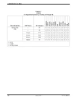
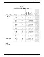
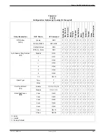
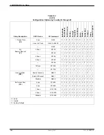
Page 149: ... modem has been approved for use in that country Consult your sales representative Each modem is shipped from the factory with a specific country code The ability to change the country code is not accessible to the user If the modem is approved for use in the country configuration options for the North America country code shown in Table H 2 are valid in Argentina Bahamas Bermuda Bolivia Brazil Br...

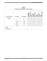
Page 150: ... ÁÁ ÁÁ VÁÁ ÁÁ I ÁÁ ÁÁ I ÁÁ ÁÁ I ÁÁ ÁÁ V ÁÁ ÁÁ V ÁÁ ÁÁ V ÁÁ ÁÁ V ÁÁ ÁÁ I ÁÁ ÁÁ V ÁÁ ÁÁ V Á Á I ÁÁ ÁÁ V ÁÁÁÁÁÁÁÁÁ ÁÁÁÁÁÁÁÁÁ ÁÁÁÁÁÁÁ ÁÁÁÁÁÁÁ 8 ÁÁÁÁÁÁÁ ÁÁÁÁÁÁÁ S0 8 ÁÁ ÁÁ V ÁÁ ÁÁ I ÁÁ ÁÁ I ÁÁ ÁÁ I ÁÁ ÁÁ V ÁÁ ÁÁ V ÁÁ ÁÁ V ÁÁ ÁÁ V ÁÁ ÁÁ I ÁÁ ÁÁ V ÁÁ ÁÁ V Á Á I ÁÁ ÁÁ V ÁÁÁÁÁÁÁÁÁ ÁÁÁÁÁÁÁÁÁ ÁÁÁÁÁÁÁÁÁ ÁÁÁÁÁÁÁ ÁÁÁÁÁÁÁ ÁÁÁÁÁÁÁ 10 ÁÁÁÁÁÁÁ ÁÁÁÁÁÁÁ ÁÁÁÁÁÁÁ S0 10 ÁÁ ÁÁ ÁÁ V ÁÁ ÁÁ ÁÁ I ÁÁ ÁÁ ÁÁ I ÁÁ ÁÁ ÁÁ I ÁÁ ÁÁ ...

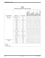
Page 151: ...ÁÁÁÁÁÁÁ S7 90 ÁÁ ÁÁ I ÁÁ ÁÁ VÁÁ ÁÁ I ÁÁ ÁÁ V ÁÁ ÁÁ I ÁÁ ÁÁ I ÁÁ ÁÁ I ÁÁ ÁÁ I ÁÁ ÁÁ I ÁÁ ÁÁ I ÁÁ ÁÁ I Á Á I ÁÁ ÁÁ I ÁÁÁÁÁÁÁÁÁ ÁÁÁÁÁÁÁÁÁ ÁÁÁÁÁÁÁ ÁÁÁÁÁÁÁ 120 sec ÁÁÁÁÁÁÁ ÁÁÁÁÁÁÁ S7 120 ÁÁ ÁÁ I ÁÁ ÁÁ I ÁÁ ÁÁ I ÁÁ ÁÁ I ÁÁ ÁÁ I ÁÁ ÁÁ I ÁÁ ÁÁ I ÁÁ ÁÁ I ÁÁ ÁÁ I ÁÁ ÁÁ I ÁÁ ÁÁ I Á Á I ÁÁ ÁÁ I ÁÁÁÁÁÁÁÁÁ ÁÁÁÁÁÁÁÁÁ ÁÁÁÁÁÁÁÁÁ ÁÁÁÁÁÁÁ ÁÁÁÁÁÁÁ ÁÁÁÁÁÁÁ ÁÁÁÁÁÁÁ ÁÁÁÁÁÁÁ ÁÁÁÁÁÁÁ S7 135 ÁÁ ÁÁ ÁÁ I ÁÁ ÁÁ ÁÁ I ÁÁ ÁÁ ÁÁ ...

Page 152: ...ÁÁÁÁÁÁÁ ÁÁÁÁÁÁÁ ÁÁÁÁÁÁÁ T3 ÁÁ ÁÁ VÁÁ ÁÁ FÁÁ ÁÁ V ÁÁ ÁÁ V ÁÁ ÁÁ V ÁÁ ÁÁ V ÁÁ ÁÁ V ÁÁ ÁÁ V ÁÁ ÁÁ F ÁÁ ÁÁ F ÁÁ ÁÁ V Á Á V ÁÁ ÁÁ V ÁÁÁÁÁÁÁÁÁ ÁÁÁÁÁÁÁÁÁ ÁÁÁÁÁÁÁ ÁÁÁÁÁÁÁ 10 min ÁÁÁÁÁÁÁ ÁÁÁÁÁÁÁ T10 ÁÁ ÁÁ VÁÁ ÁÁ VÁÁ ÁÁ V ÁÁ ÁÁ V ÁÁ ÁÁ V ÁÁ ÁÁ V ÁÁ ÁÁ V ÁÁ ÁÁ V ÁÁ ÁÁ V ÁÁ ÁÁ V ÁÁ ÁÁ V Á Á V ÁÁ ÁÁ V ÁÁÁÁÁÁÁÁÁ ÁÁÁÁÁÁÁÁÁ ÁÁÁÁÁÁÁ ÁÁÁÁÁÁÁ 30 min ÁÁÁÁÁÁÁ ÁÁÁÁÁÁÁ T30 ÁÁ ÁÁ V ÁÁ ÁÁ V ÁÁ ÁÁ V ÁÁ ÁÁ V ÁÁ ÁÁ V ÁÁ ÁÁ V...

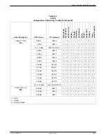
Page 153: ...ÁÁ ÁÁ ÁÁ V ÁÁ ÁÁ ÁÁ V Á Á Á V ÁÁ ÁÁ ÁÁ V ÁÁÁÁÁÁÁÁÁ ÁÁÁÁÁÁÁÁÁ ÁÁÁÁÁÁÁÁÁ ÁÁÁÁÁÁÁ ÁÁÁÁÁÁÁ ÁÁÁÁÁÁÁ 10 dBm ÁÁÁÁÁÁÁ ÁÁÁÁÁÁÁ ÁÁÁÁÁÁÁ I10 ÁÁ ÁÁ ÁÁ F ÁÁ ÁÁ ÁÁ I ÁÁ ÁÁ ÁÁ V ÁÁ ÁÁ ÁÁ F ÁÁ ÁÁ ÁÁ F ÁÁ ÁÁ ÁÁ V ÁÁ ÁÁ ÁÁ V ÁÁ ÁÁ ÁÁ V ÁÁ ÁÁ ÁÁ F ÁÁ ÁÁ ÁÁ F ÁÁ ÁÁ ÁÁ F Á Á Á V ÁÁ ÁÁ ÁÁ V ÁÁÁÁÁÁÁÁÁ ÁÁÁÁÁÁÁÁÁ ÁÁÁÁÁÁÁ ÁÁÁÁÁÁÁ 11 dBm ÁÁÁÁÁÁÁ ÁÁÁÁÁÁÁ I11 ÁÁ ÁÁ VÁÁ ÁÁ I ÁÁ ÁÁ V ÁÁ ÁÁ V ÁÁ ÁÁ V ÁÁ ÁÁ F ÁÁ ÁÁ V ÁÁ ÁÁ F ÁÁ Á...

Page 154: ...ÁÁÁÁÁ ÁÁÁÁÁÁÁ ÁÁÁÁÁÁÁ 10 dBm ÁÁÁÁÁÁÁ ÁÁÁÁÁÁÁ ÁÁÁÁÁÁÁ S45 10 ÁÁ ÁÁ ÁÁ F ÁÁ ÁÁ ÁÁ F ÁÁ ÁÁ ÁÁ V ÁÁ ÁÁ ÁÁ F ÁÁ ÁÁ ÁÁ V ÁÁ ÁÁ ÁÁ V ÁÁ ÁÁ ÁÁ I ÁÁ ÁÁ ÁÁ V ÁÁ ÁÁ ÁÁ V ÁÁ ÁÁ ÁÁ V ÁÁ ÁÁ ÁÁ V Á Á Á V ÁÁ ÁÁ ÁÁ V ÁÁÁÁÁÁÁÁÁ ÁÁÁÁÁÁÁÁÁ ÁÁÁÁÁÁÁÁÁ ÁÁÁÁÁÁÁ ÁÁÁÁÁÁÁ ÁÁÁÁÁÁÁ 11 dBm ÁÁÁÁÁÁÁ ÁÁÁÁÁÁÁ ÁÁÁÁÁÁÁ S45 11 ÁÁ ÁÁ ÁÁ V ÁÁ ÁÁ ÁÁ V ÁÁ ÁÁ ÁÁ V ÁÁ ÁÁ ÁÁ V ÁÁ ÁÁ ÁÁ V ÁÁ ÁÁ ÁÁ F ÁÁ ÁÁ ÁÁ I ÁÁ ÁÁ ÁÁ F ÁÁ ÁÁ ÁÁ V ÁÁ ÁÁ ÁÁ ...

Page 155: ...Á ÁÁÁÁÁÁÁ 8 ÁÁÁÁÁÁÁ ÁÁÁÁÁÁÁ S0 8 ÁÁ ÁÁ I ÁÁ ÁÁ I ÁÁ ÁÁ V ÁÁ ÁÁ V ÁÁ ÁÁ V ÁÁ ÁÁ V ÁÁ ÁÁ V ÁÁ ÁÁ I ÁÁ ÁÁ V ÁÁ ÁÁ I ÁÁ ÁÁ V Á Á V ÁÁ ÁÁ V ÁÁÁÁÁÁÁÁÁ ÁÁÁÁÁÁÁÁÁ ÁÁÁÁÁÁÁ ÁÁÁÁÁÁÁ 10 ÁÁÁÁÁÁÁ ÁÁÁÁÁÁÁ S0 10 ÁÁ ÁÁ I ÁÁ ÁÁ I ÁÁ ÁÁ V ÁÁ ÁÁ I ÁÁ ÁÁ V ÁÁ ÁÁ V ÁÁ ÁÁ V ÁÁ ÁÁ I ÁÁ ÁÁ V ÁÁ ÁÁ I ÁÁ ÁÁ V Á Á V ÁÁ ÁÁ V ÁÁÁÁÁÁÁÁÁ ÁÁÁÁÁÁÁÁÁ ÁÁÁÁÁÁÁÁÁ Dialer Type ÁÁÁÁÁÁÁ ÁÁÁÁÁÁÁ ÁÁÁÁÁÁÁ Tone ÁÁÁÁÁÁÁ ÁÁÁÁÁÁÁ ÁÁÁÁÁÁÁ T ÁÁ ÁÁ...

Page 156: ...ÁÁÁÁÁ S7 90 ÁÁ ÁÁ I ÁÁ ÁÁ I ÁÁ ÁÁ V ÁÁ ÁÁ V ÁÁ ÁÁ V ÁÁ ÁÁ V ÁÁ ÁÁ I ÁÁ ÁÁ V ÁÁ ÁÁ I ÁÁ ÁÁ F ÁÁ ÁÁ V Á Á V ÁÁ ÁÁ I ÁÁÁÁÁÁÁÁÁ ÁÁÁÁÁÁÁÁÁ ÁÁÁÁÁÁÁ ÁÁÁÁÁÁÁ 120 sec ÁÁÁÁÁÁÁ ÁÁÁÁÁÁÁ S7 120 ÁÁ ÁÁ I ÁÁ ÁÁ I ÁÁ ÁÁ V ÁÁ ÁÁ I ÁÁ ÁÁ I ÁÁ ÁÁ V ÁÁ ÁÁ I ÁÁ ÁÁ I ÁÁ ÁÁ I ÁÁ ÁÁ I ÁÁ ÁÁ V Á Á V ÁÁ ÁÁ I ÁÁÁÁÁÁÁÁÁ ÁÁÁÁÁÁÁÁÁ ÁÁÁÁÁÁÁÁÁ ÁÁÁÁÁÁÁ ÁÁÁÁÁÁÁ ÁÁÁÁÁÁÁ ÁÁÁÁÁÁÁ ÁÁÁÁÁÁÁ ÁÁÁÁÁÁÁ S7 135 ÁÁ ÁÁ ÁÁ I ÁÁ ÁÁ ÁÁ I ÁÁ ÁÁ ÁÁ V...

Page 157: ...ÁÁÁÁÁÁ ÁÁÁÁÁÁÁ ÁÁÁÁÁÁÁ T3 ÁÁ ÁÁ ÁÁ V ÁÁ ÁÁ ÁÁ V ÁÁ ÁÁ ÁÁ V ÁÁ ÁÁ ÁÁ V ÁÁ ÁÁ ÁÁ V ÁÁ ÁÁ ÁÁ V ÁÁ ÁÁ ÁÁ V ÁÁ ÁÁ ÁÁ V ÁÁ ÁÁ ÁÁ V ÁÁ ÁÁ ÁÁ V ÁÁ ÁÁ ÁÁ V Á Á Á V ÁÁ ÁÁ ÁÁ V ÁÁÁÁÁÁÁÁÁ ÁÁÁÁÁÁÁÁÁ ÁÁÁÁÁÁÁ ÁÁÁÁÁÁÁ 10 min ÁÁÁÁÁÁÁ ÁÁÁÁÁÁÁ T10 ÁÁ ÁÁ VÁÁ ÁÁ VÁÁ ÁÁ V ÁÁ ÁÁ V ÁÁ ÁÁ V ÁÁ ÁÁ V ÁÁ ÁÁ V ÁÁ ÁÁ V ÁÁ ÁÁ V ÁÁ ÁÁ V ÁÁ ÁÁ V Á Á V ÁÁ ÁÁ V ÁÁÁÁÁÁÁÁÁ ÁÁÁÁÁÁÁÁÁ ÁÁÁÁÁÁÁ ÁÁÁÁÁÁÁ 30 min ÁÁÁÁÁÁÁ ÁÁÁÁÁÁÁ T30 ÁÁ ÁÁ VÁ...

Page 158: ...ÁÁÁÁÁÁÁÁÁ ÁÁÁÁÁÁÁÁÁ ÁÁÁÁÁÁÁÁÁ ÁÁÁÁÁÁÁ ÁÁÁÁÁÁÁ ÁÁÁÁÁÁÁ 10 dBm ÁÁÁÁÁÁÁ ÁÁÁÁÁÁÁ ÁÁÁÁÁÁÁ I10 ÁÁ ÁÁ ÁÁ F ÁÁ ÁÁ ÁÁ V ÁÁ ÁÁ ÁÁ V ÁÁ ÁÁ ÁÁ F ÁÁ ÁÁ ÁÁ V ÁÁ ÁÁ ÁÁ F ÁÁ ÁÁ ÁÁ F ÁÁ ÁÁ ÁÁ V ÁÁ ÁÁ ÁÁ V ÁÁ ÁÁ ÁÁ V ÁÁ ÁÁ ÁÁ V Á Á Á V ÁÁ ÁÁ ÁÁ V ÁÁÁÁÁÁÁÁÁ ÁÁÁÁÁÁÁÁÁ ÁÁÁÁÁÁÁÁÁ ÁÁÁÁÁÁÁ ÁÁÁÁÁÁÁ ÁÁÁÁÁÁÁ 11 dBm ÁÁÁÁÁÁÁ ÁÁÁÁÁÁÁ ÁÁÁÁÁÁÁ I11 ÁÁ ÁÁ ÁÁ V ÁÁ ÁÁ ÁÁ V ÁÁ ÁÁ ÁÁ V ÁÁ ÁÁ ÁÁ V ÁÁ ÁÁ ÁÁ V ÁÁ ÁÁ ÁÁ V ÁÁ ÁÁ ÁÁ V ÁÁ ÁÁ...

Page 159: ...ÁÁ ÁÁ V ÁÁ ÁÁ V ÁÁ ÁÁ V ÁÁ ÁÁ F ÁÁ ÁÁ V Á Á V ÁÁ ÁÁ V ÁÁÁÁÁÁÁÁÁ ÁÁÁÁÁÁÁÁÁ ÁÁÁÁÁÁÁ ÁÁÁÁÁÁÁ 10 dBm ÁÁÁÁÁÁÁ ÁÁÁÁÁÁÁ S45 10 ÁÁ ÁÁ FÁÁ ÁÁ VÁÁ ÁÁ V ÁÁ ÁÁ F ÁÁ ÁÁ V ÁÁ ÁÁ V ÁÁ ÁÁ V ÁÁ ÁÁ V ÁÁ ÁÁ F ÁÁ ÁÁ V ÁÁ ÁÁ V Á Á V ÁÁ ÁÁ V ÁÁÁÁÁÁÁÁÁ ÁÁÁÁÁÁÁÁÁ ÁÁÁÁÁÁÁ ÁÁÁÁÁÁÁ 11 dBm ÁÁÁÁÁÁÁ ÁÁÁÁÁÁÁ S45 11 ÁÁ ÁÁ V ÁÁ ÁÁ V ÁÁ ÁÁ V ÁÁ ÁÁ V ÁÁ ÁÁ V ÁÁ ÁÁ V ÁÁ ÁÁ V ÁÁ ÁÁ V ÁÁ ÁÁ V ÁÁ ÁÁ V ÁÁ ÁÁ V Á Á V ÁÁ ÁÁ V ÁÁÁÁÁÁÁÁÁ ÁÁ...

Page 160: ...COMSPHERE 3821Plus Modem H 12 January 1999 3821 A2 GB20 40 This page intentionally left blank ...

Page 161: ...ng process with the calling modem ASCII This code American Standard Code for Information Interchange is a 7 bit code which establishes compatibility between data services ASCII is the standard for data transmission over telephone lines The ASCII code consists of 32 control characters nondisplayed and 96 displayed characters asymmetric rate In V 34 the ability of a device to transmit at a different...

Page 162: ...h is the smallest unit of information represents a one or a zero sometimes called mark or space bps Bits per second Indicates the speed at which bits are transmitted across a data connection buffer A storage device used to compensate for differences in the data flow rate when transmitting data from one device to another byte A sequence of successive bits usually eight handled as a unit in data tra...

Page 163: ...ata mode the modem transmits and receives data instead of accepting commands DB 25 connector A 25 pin connector that is used to connect a cable which enables communications between two devices dBm A decibel referenced to one milliwatt into 600 ohms This unit measures relative signal power DCE The equipment Data Communications Equipment or Data Circuit Terminating Equipment that provides the functi...

Page 164: ... position interface between data terminal equipment and data communications automatic calling equipment EPROM Erasable programmable read only memory error control An algorithm used to correct data transmission errors escape sequence Default setting is This sequence lets you switch your modem from Data mode to Command mode ETC Enhanced Throughput Cellular A proprietary analog cellular transmission ...

Page 165: ...DCP or SDCP that glows in response to the presence of a certain condition e g Alrm local analog loopback Test in which the modem s transmit VF signal is looped to its receiver long space disconnect A disconnect can occur if the modem receives an extended space from a remote modem for example when a remote modem is commanded to disconnect it transmits a continuous space to the modem before disconne...

Page 166: ...rol and flow control during data transmission PSTN Public Switched Telephone Network A network shared among many users who can use telephones to establish connections between two points Also known as dial network pulse dialing One of two dialing methods in which telephone numbers are sent as pulses brief changes in voltage or current intensity across the telephone line Rotary telephones use pulse ...

Page 167: ...erating full duplex with asynchronous or synchronous data at 1200 or 2400 bps over the dial network PSTN V 25bis A dialing protocol that permits direct and stored number dialing in asynchronous bisynchronous or HDLC modes V 27ter A fax communications standard for modems operating half duplex with synchronous data at 2400 and 4800 bps V 29 A fax communications standard for modems operating half dup...

Page 168: ...te diagnostic loopback tests VF Voice Frequency The part of the audio frequency range used to transmit voice sound usually 300 Hz to 3400 Hz This band is used by the modem for its modulated signal XOFF A character that tells the DTE or modem to stop transmitting data XON A character that tells the DTE or modem to start or resume transmitting data ...

Page 169: ...trol 3 23 4 7 D DTR Action 3 21 4 8 F Factory Defaults 4 8 G V 22bis Guard Tone 3 36 4 8 I Dial Transmit Level 4 9 J Dial Transmit Type 3 35 4 9 L Leased Mode 3 37 4 9 M Async Sync Mode and DTE Dialer Type 3 19 3 25 4 10 Q Async Sync Mode and DTE Dialer Type 3 19 3 25 4 10 R RTS Action 3 22 4 10 S DSR Control 3 21 4 11 T Tests 4 11 T4 T5 Receive Remote Loopback Response 3 44 V View Configuration O...

Page 170: ...swer commands V 25bis F 3 Call Request commands V 25bis F 2 Call Response V 25bis F 2 Call Setup branch 3 9 Call Waiting 4 3 Callback Security 7 11 enabling 7 7 Carriage Return Character 3 26 Carrier On Level 3 38 Cellular Mobile 3 46 Cellular Enhancement 3 43 Cellular Enhancement S91 4 25 Cellular RJ11 Adapt 3 46 cellular transmit level 4 9 Change Directory 3 10 change S register 4 5 character fo...

Page 171: ...6 DTR Continuous Repeat 3 29 4 18 E echo command 4 4 Edit Password Table 7 4 Edit Strap Group 3 15 EIA 232 E pin assignments E 1 End DCP option 3 17 Enhanced Throughput Cellular ETC 3 35 4 8 4 9 Entry Wait Time 7 9 equipment list G 1 equipment required 2 1 Erase All Passwords 7 8 error codes result codes B 1 error control 3 39 Error Control Fallback Character 3 40 Error Control Fallback Character ...

Page 172: ...Line Dialer 3 30 Linefeed Character 3 27 load Active Operating area 4 6 Local Analog Loop 3 13 Local Digital Loop 3 14 Long Space Disconnect 3 32 LSD Control 3 23 LSD Control AT C 4 7 M Make Busy 3 47 Make Busy Via DTR 3 33 Max Frame Size 3 43 menu tree A 1 overview 3 2 remote 6 2 MNP5 Data Compression 3 40 MNP5 Data Compression AT C 4 13 Modem Select branch 3 7 Modem to Modem Flow Control 3 42 Mo...

Page 173: ... RJ11 gang box 2 2 RTS Action R 3 22 4 10 RTS to CTS Delay S26 4 18 RTS CTS Delay 3 23 RX Buff Disc Delay 3 43 S S registers changing 4 5 displaying 4 5 list of 4 16 S0 Auto Answer Ring Number 3 30 4 16 S2 Escape Character 3 25 4 1 4 16 S3 Carriage Return Character 3 26 4 16 S4 Line Feed Character 3 27 4 17 S5 Backspace Character 3 26 4 17 S6 Blind Dial Pause 3 30 4 17 S7 No Answer Timeout 3 31 4 ...

Page 174: ...meout S18 4 18 tests AT T 4 11 timeout for no answer S7 4 17 Train Time 3 36 Train Time S43 4 19 Transmit Clock Source 3 24 transmit level AT I 4 9 transmit type AT J 4 9 troubleshooting C 1 two wire leased line connection 2 2 E 2 TX Buff Disc Delay 3 43 U UNIX factory default for 4 8 upgrade instructions 3 49 C 5 V V 21 or V 22 modulation 4 3 V 22bis Guard Tone 3 36 V 25bis applications 4 27 V 25...

Page 175: ...00282600 ...

Reviews: