Power Up a FrameSaver NP 64+
Make Power Connections
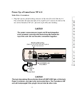
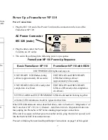
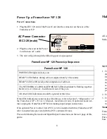
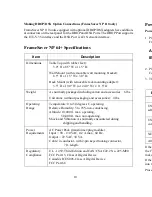
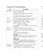
1. Plug the 2-pin keyed and locking connector at the end of the cord from the AC
Power Pack into the right-most pins of the 4-pin Power Connector located on the
rear of the FrameSaver NP 64+, just to the right of the alert marking.
CAUTION
The power connectors are keyed and fit easily together
when oriented correctly with the locking clip toward the
top of the unit. Do not force the connectors together.
CAUTION
The 2-pin keyed plug fits easily into the two RIGHT-SIDE pins of the 4-pin
Power Connector, and must only be inserted there. The FrameSaver NP
unit will be damaged if the plug is forced into the other side.
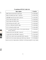
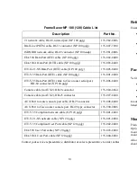
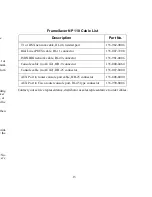
Contact your service representative, distributor or sales representative to order cables.
D ATA P O R T
S EE
U SE RS
M AN U AL
P O W ER
P AC
O
N
1 2 3 4 5 6 7 8 9 1 0 1 1 1 2
D LC I
x1
x100
x10
D IG ITS
2-Pin
Connector
from
Pow er Pack
Plug into RIG H T side
Pins O NLY
Blocking Safety Plug
(R e m o ve o n ly w h e n in sta llin g o p tio n a l
P o w e r C o n tro l U n it)
FrameSaver NP 64+ Cable List
Description
Part No.
DDS network cable, RJ-48, twisted pair
135-982-0006
Dial Line (POTS) cable, RJ-11 connector
135-007-7200
ISDN BRI network cable, RJ-49 connector
135-981-0006
EIA-232 Data Port (DTE) cable
135-000-0400
EIA-530 Data Port (DTE) cable
135-002-0400
EIA-530A Data Port (DTE) cable
135-003-0400
ITU-X.21-NS Data Port (DTE) cable
135-005-0400
ITU-V.35 Data Port (DTE) cable
135-001-0400
ITU-V.35 Data Port (DTE) cable to Cisco router serial port,
HD-60 connector
135-006-0400
Console cable (to AUX2), DB-9 connector
135-000-0464
Console cable (to AUX2), DB-25 connector
135-007-0400
AUX Port to router console port cable, DB-25 connector
135-008-0400
AUX Port to Cisco router console port, RJ-45 type connector
135-990-0006
13
4


