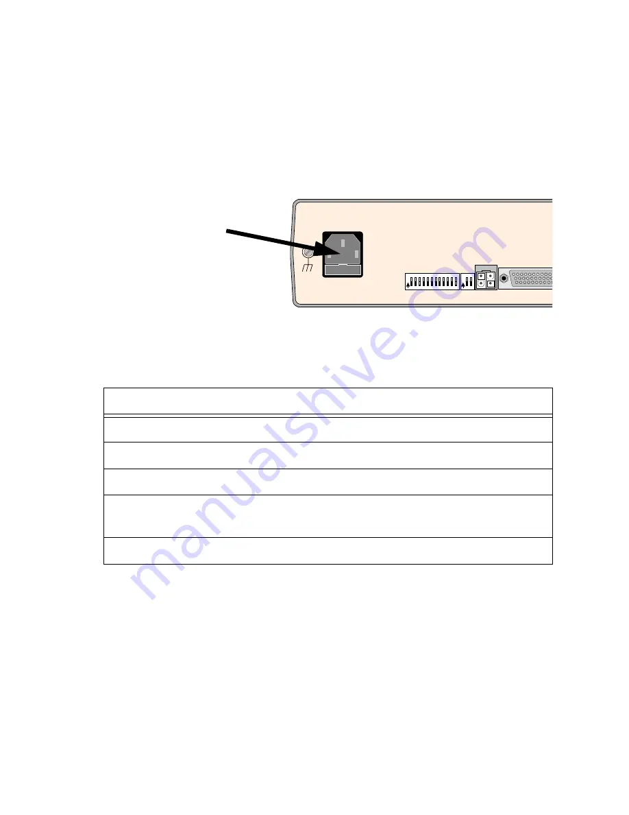
Power Up a FrameSaver NP 120
Power Connections
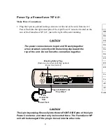
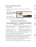
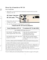
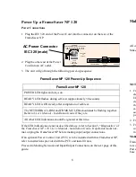
1. Plug the IEC 320 end of the Power Cord into the connector on the rear of the
FrameSaver NP.
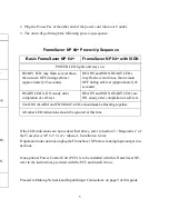
2. Plug the other end of the Power
Cord into an AC outlet.
3. The unit will go through the following power-up sequence
FrameSaver NP 120 Power-Up Sequence
If the LED indications are not as described above, refer to Section 5, “Diagnostics” of
the FrameSaver NP 120 User’s Manual - Installation Guide. If operation looks nor-
mal, unplug the FrameSaver NP before making input/output connections.
If an optional Power Control Unit (PCU) is to be installed with this FrameSaver NP,
refer to instructions provided with the PCU and install it now.
Proceed to Making Network and Input/Output Connections on the next page of this
guide.
Making Network and Input/Output Connections
CAUTION
Be sure you remove AC power from the FrameSaver NP
before attaching input and output cables.
All connectors are located on the FrameSaver NP’s rear panel.
Make all the necessary connections using the cables listed for that model.
CAUTION
Use caution when connecting to an AUX Port. AUX Port
connectors are similar to the Network connectors.
Accidental connection of either of the AUX Ports to a
Network facility may damage the AUX Port electrical
interface.
NOTES:
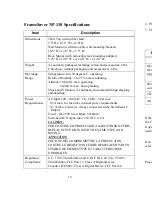
1. FrameSaver NP 64+, 100, and 120 Data and User Ports support numerous
electrical interface types; ITU-V.35, EIA-530, EIA-530-A, ITU-X.21-NS and
EIA-232 (FrameSaver NP 64+ only). The Data Port connector is a DB-44 high
density female. The adapter cables listed for each model are used to convert from
the DB-44 to the appropriate connector type for the interface selected. The adapter
cable also includes a special wiring pattern at the DB-44 connector, which
automatically sets the port to the desired interface type. Refer to the tables on
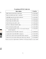
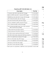
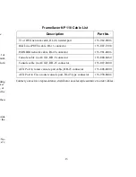
pages 13 - 15 of this guide for cable ordering information if necessary.
2. FrameSaver NP 110 User and Data Ports are configured for ITU-V.35 Interface.
3. FrameSaver NP 120 is designed for use in networks where it is not directly
connected to the local PTT’s (non-U.S.) facilities. All the Network connections are
made to the customer’s Private Network.
Making ISDN Option Connections
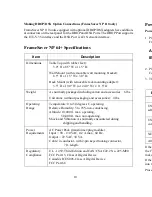
FrameSaver NP units equipped with optional ISDN adapters have additional connec-
tors on the rear panel for ISDN Line(s) and ISDN Data Port (DTE). The ISDN Data
Port supports the same electrical interface types and uses the same connector as the
base unit Data Port.
FrameSaver NP 120
POWER LED lights and stays on.
READY LED flashes during self-test (approximately 30 seconds).
READY LED is ON steady after completion of self-test.
The NETWORK ALARM and FR MGMT. LEDs should not be flashing together.
Refer to User’s Manual - Installation Guide if they are.
All other LED indications should be ignored at this time.
U S E R P O R
C O N FIG U R A TIO N
O
N
1 2 3 4 5 6 7 8 9 1 0 1 1 1 2
O
N
1 2
C O N TR O L
O U TP U T
FU S E
2 A/2 5 0V
S L O W B LO W
5 x2 0 m m
1 00 -2 40 V AC
.5A
5 0-6 0 H z
FO R C O N TIN U E D P R O TE C TIO N A G AIN S T
R IS K O F F IR E , R E P L AC E O N L Y W ITH
S A M E TY P E AN D R ATIN G O F F U S E .
"C AU TIO N"
9
8
AC Power Connector
IEC 320 (male)


