background image

13

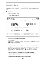
As an example, follow these steps to go to the Configuration Edit/Display menu so you 
can start setting up the unit. 

Procedure


To load a configuration for editing:

1.

From the Main Menu, press the down arrow key twice so the cursor is on 
Configuration.

2.

Press Enter to display the Configuration menu. The Load Configuration From menu 
appears.

3.

Press Enter to select Current Configuration (the cursor is already on this selection). 
The Configuration Edit/Display menu appears.

This sequence of steps would be shown as the menu selection sequence:

Main Menu

Configuration

Procedure


To save a configuration option change:

1.

Press Ctrl-a to switch to the function keys area at the bottom of the screen.

2.

Type 

s

 or 

S

 (Save) and press Enter. The Save Configuration To menu appears.

3.

Press Enter again to save your changes to the Current Configuration.

4.

Press Esc until the Configuration Edit/Display menu reappears to continue 
configuring the unit.

Press Ctrl-a, type 

m

 (MainMenu), and press Enter to return to the Main Menu.

About the Installation Procedures

There are two methods for installing and setting up the FrameSaver unit.

One person can install and set up the unit. If this is the case, see 

Full Installation 

and Setup

 on page 16

An installer can physically install and set up access to the unit, and the network 
operation center (NOC) can complete the setup. If this is the case, see 

Minimal 

Installation

 on page 14.

Summary of Contents for FrameServer SLV 9520-ILM

Page 1: ...wer On Self Test 12 Configuration Using Configuration Edit Display 12 About the Installation Procedures 13 Minimal Installation 14 Full Installation and Setup 16 Automatic Configuration 17 Connecting...

Page 2: ...0 A2 GB33 To order a paper copy of a Paradyne document or to speak with a sales representative please call 1 727 530 2000 Be sure to register your warranty at www paradyne com warranty Checking the Co...

Page 3: ...is required during installation or when test equipment is connected to the unit The front of the unit must be visible so that LEDs can be monitored Access to the front of the unit is also required in...

Page 4: ...tity Required Supplied NET RX NET TX and CPE RX CPE TX BNC to BNC coaxial Four Two LAN Ethernet 10 100BaseT straight through cable with 8 pin modular connectors One if LAN port is to be connected to a...

Page 5: ...holes The mounting brackets machine screws and self retaining nuts are supplied with the FrameSaver SLV 9520 ILM Procedure To install the FrameSaver SLV 9520 ILM in a standard rack 1 Determine the gen...

Page 6: ...ough the keyed holes of the bracket Lower the unit onto the screws 8 Put a machine screw through the top hole of each bracket and tighten the screw Tighten the bottom screws FrameSaverTM SLV 95 80 AI...

Page 7: ...cable into the power receptacle on the back of the FrameSaver SLV 9520 ILM Fix the cable to the rail with a cable tie or other strain relief device 3 Connect the other end of the power cable to a gro...

Page 8: ...ight through cable Procedure To install the cable with a terminal or PC 1 Press the 25 pin connector of the cable onto the TERMINAL PORT socket on the back of the FrameSaver SLV 9520 ILM If the cable...

Page 9: ...onStatus Device Name IP Address Status Discovery Source PVC Connection Status Source Link DLCI EDLCI Status Primary Destination Status Alternate Destination Status IPRoutingTable Destination Mask Gate...

Page 10: ...ervice Level Verification General Network Physical Frame Relay PPP DLCI Records T3 User Ports Physical Frame Relay PPP DLCI Records PVC Connections Source Link DLCI EDLCI Primary Destination Link DLCI...

Page 11: ...Back Mode Standard Mode Select Software Release Current Release Alternate Release Switch Reset LMI Packet Capture Utility Capture Interface Packet Capture Start Stop Status Packets in Buffer Display L...

Page 12: ...he System and Test Status screen Main Menu Status System and Test Status Configuration Using Configuration Edit Display The FrameSaver unit should operate using the default factory set configuration o...

Page 13: ...tion change 1 Press Ctrl a to switch to the function keys area at the bottom of the screen 2 Type s or S Save and press Enter The Save Configuration To menu appears 3 Press Enter again to save your ch...

Page 14: ...used select the Ethernet Port Options Screen Enable the interface Respond Yes to the prompt Would you like to set the Node s Default IP Destination to Ethernet and configure the following Enter the IP...

Page 15: ...complete the NOC can now remotely access the unit for additional configuration Completing Setup of the Unit From the NOC Procedure 1 Access the remote FrameSaver unit on the dedicated network managem...

Page 16: ...e network cable see Connecting to the Network on page 17 The FrameSaver unit starts discovering DLCIs see Automatic Configuration on page 17 5 If SNMP traps are wanted set up managers and select the d...

Page 17: ...w the Frame Relay Discovery Mode can be changed No automatic configuration occurs until the network cable is connected If you do not want management links configured or automatic configuration change...

Page 18: ...If yes the network interface is set up correctly and is ready to pass data If no check that both ends of the network cable are properly seated then verify that the network physical options are configu...

Page 19: ...that the entire path from the unit to the NMS is functioning To run the IP Ping test SNMP trap managers must have been configured for the FrameSaver unit One of those trap managers must be the NOC NM...

Page 20: ...the LAN port to a NIC use a 10BaseT crossover cable 2 Insert the 8 pin modular connector of the cable into the LAN socket on the back of the FrameSaver SLV 9520 ILM It locks in place when it is fully...

Page 21: ...erational If no check that both ends of the cable are properly seated and secured Verify that the T3 User Ports Physical options are configured correctly Check Health and Status in the left column of...

Page 22: ...r a damaged cable Recheck LMI status you may need to contact your service provider Next check the DLCI s status Checking PVC Connections Procedure Check PVC connections to verify that all PVCs includi...

Page 23: ...product Special cables which may be required by the regulatory inspection authority for the installation site are the responsibility of the customer Use a minimum 26 AWG UL Listed or CSA Certified li...

Page 24: ...nger d explosion s il y a remplacement incorrect de la batterie Remplacer uniquement avec une batterie du m me type Mettre au rebut les batteries usag es conform ment aux instructions du fabricant EMI...

Page 25: ...ue your service temporarily If possible they will notify you in advance But if advance notice is not practical you will be notified as soon as possible You will be advised of your right to file a comp...

Page 26: ...ier Any repairs or alterations made by the user to this equipment or equipment malfunctions may give the telecommunications company cause to request to disconnect the equipment Users should ensure for...

Page 27: ...800 870 2221 Outside the U S A call 1 727 530 2340 Document Feedback We welcome your comments and suggestions about this document Please mail them to Technical Publications Paradyne Corporation 8545 1...

Page 28: ...28 9520 A2 GN11 10 9520 A2 GN11 10...

Reviews: