1. Installation
4200-A2-GN20-10
October 2002
1-11
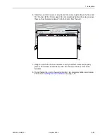
6. Install two wood screws (not provided) at the same height above the floor and
18.75 inches (476.25 mm ) apart. Do not completely tighten the screws. Leave
them so their heads are about 1/4 inch (6 mm) from the wall.
7. Hang the unit from the wood screws to verify that the screws are properly
placed. The screws should freely slide into the top of the key slots in the
brackets.
8. Do not fasten the unit to the wall until after it is completely cabled and tested.
Proceed to
Installing the Uplink Module
on page 1-13.
02-17254
18.75 in (476.25 mm)
Summary of Contents for GranDSLAM 4200
Page 1: ...GranDSLAM 4200 ATM Stackable DSLAM Installation Guide Document No 4200 A2 GN20 10 October 2002...
Page 6: ...E October 2002 4200 A2 GN20 10...
Page 42: ...2 Cabling 2 18 October 2002 4200 A2 GN20 10...
Page 50: ...4 Configuration 4 6 October 2002 4200 A2 GN20 10...
Page 58: ...A Connectors and Pin Assignments A 8 October 2002 4200 A2 GN20 10...

