2. Cabling
4200-A2-GN20-10
October 2002
2-5
3. Connect the other end of the cable to the appropriate network equipment such
as a multiplexer.
Procedure
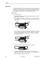
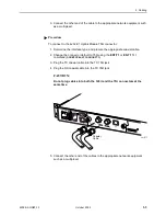
To connect to the 4202 E1 Uplink Module 75
Ω
connector:
1. Determine the interface type, and procure the appropriate coaxial cable.
2. Change the connector default to 75
Ω
using the ENT-T1 or ED-T1 TL1
command
(
LINETYPE=G703SHORT75
).
3. Plug the TX coaxial cable into the TX 75
Ω
jack.
4. Plug the RX coaxial cable into the TX 75
Ω
jack.
CAUTION:
Do not plug cables into both the 120
Ω
and the
75
Ω
connectors
at the
same time.
5. Connect the other end of the cables to the appropriate network equipment
such as a multiplexer.
02-17277
Coaxial
Cable
1
12
13
24
4
8
16
20
POWER
A
ALARM
RTN -48V
DC
BITS
MGMT
CONSOLE
S
TA
T
U
S
U
P
L
IN
K
A
LR
M
TES
T
B
A
3.5 A 60
B
E1 MODU
LE
4202
TX
RX
120
Ω
75
Ω
Summary of Contents for GranDSLAM 4200
Page 1: ...GranDSLAM 4200 ATM Stackable DSLAM Installation Guide Document No 4200 A2 GN20 10 October 2002...
Page 6: ...E October 2002 4200 A2 GN20 10...
Page 42: ...2 Cabling 2 18 October 2002 4200 A2 GN20 10...
Page 50: ...4 Configuration 4 6 October 2002 4200 A2 GN20 10...
Page 58: ...A Connectors and Pin Assignments A 8 October 2002 4200 A2 GN20 10...


