C. Technical Specifications
C-2
October
2002
4200-A2-GN20-10
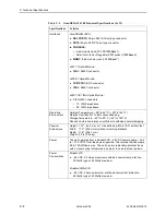
Interfaces
GranDSLAM 4200:
DSL PORTS: 50-pin RJ21X Telco-type connector
POTS: 50-pin RJ21X Telco-type connector
CONSOLE:
– 8-pin modular jack (10/100/1000BaseT)
– Small Form-factor Pluggable (SFP) socket (1000BaseX)
MGMT: 8-pin modular jack (10/100BaseT)
4201 T1 Uplink Module:
100
Ω
: RJ48C connector
4202 E1 Uplink Module:
TX/RX 75
Ω
: BNC connector
120
Ω
: RJ48C connector
4203 T1/E1 IMA Uplink Module:
1
−
8 RJ48C connectors
– T1: 100
Ω
impedance
– E1: 120
Ω
impedance
Operating
Environment
Ambient Temperature: – 40
°
to 65
°
C (– 40
°
to 149
°
F)
Relative Humidity: 5% to 95% noncondensing
Storage Temperature: – 40
°
to 85
°
C (– 40
°
to 185
°
F)
Shock and vibration tolerance sufficient to withstand normal shipping
Physical
Dimensions
Height: 1.75
″
(44.5 mm, or 1U as defined in EIA-310-C) without feet
Width: 17.2
″
(436.9 mm ) without mounting brackets
Depth: 11.8
″
(299.7 mm)
Weight: 8.5 lb (3.86 kg)
Power
The unit operates from a standard CO – 48 VDC power supply (– 40.5
to – 57.0 VDC). Dual feeds are supported. The terminal block accepts
28 to 18 AWG bare wire. The unit has two replacable, external fuses
with a visual spring indicator and an alarm in case the fuse is blown.
Power
Consumption
Model 4210:
– 48 VDC, 3.5 Amps maximum sustained overcurrent protection,
30 Watts typical, 32 Watts maximum
Models 4220/4230:
– 48 VDC, 4 Amps maximum sustained overcurrent protection,
48 Watts typical, 53 Watts maximum
Table C-1.
GranDSLAM 4200 Technical Specifications (2 of 2)
Specifications
Criteria
Summary of Contents for GranDSLAM 4200
Page 1: ...GranDSLAM 4200 ATM Stackable DSLAM Installation Guide Document No 4200 A2 GN20 10 October 2002...
Page 6: ...E October 2002 4200 A2 GN20 10...
Page 42: ...2 Cabling 2 18 October 2002 4200 A2 GN20 10...
Page 50: ...4 Configuration 4 6 October 2002 4200 A2 GN20 10...
Page 58: ...A Connectors and Pin Assignments A 8 October 2002 4200 A2 GN20 10...


