background image

 6

5020-A2-GN10-60

April 2000

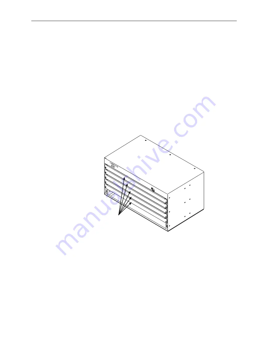
6-Slot 5016 POTS Splitter Chassis Package Checklist

Verify that your 6-slot POTS splitter chassis package contains the following:

6-slot POTS splitter chassis with five filler panels. Each filler panel is
attached to the chassis with two 1/4-turn fasteners. Keep filler panels
installed in all unused slots.

Two brackets for 19

 racks and two brackets for 23

 racks

Small plastic bag with:

— Six #10-32 x 1/4

 Phillips flat-head mounting screws

— Four #10-32 x 1/2

 Phillips-head mounting screws

— Four #12-24 x 1/2

Phillips-head mounting screws

— Four #12-24 self-retaining nuts

— Four black rubber feet (discard)

99-15430-02

CO POTS Splitter
6-Slot Chassis

Filler
Panels

TM

Summary of Contents for Hotwire 5020

Page 1: ...Plain Old Telephone Service requires the installation of a POTS splitter at the central office CO The CO POTS splitter separates the DSL and POTS frequencies Four CO POTS splitter models are available...

Page 2: ...order additional product documentation Paradyne documents are also available on the World Wide Web at www paradyne com Select Library Technical Manuals Hotwire DSL MVL Systems Installation Overview I...

Page 3: ...s each One Y cable Two POTS splitter cards to six port cards 6020 MVL 12 port Card p 8310 MVL 4 port Card 8600 front connector servicing 12 ports One straight through cable One POTS splitter card to t...

Page 4: ...A small 1 or 2 Phillips screwdriver to tighten the POTS splitter card fasteners A large 3 or 4 Phillips screwdriver to install the chassis into a rack A flat blade screwdriver to install the chassis...

Page 5: ...TS splitter chassis Two brackets for 19 racks and two brackets for 23 racks Small plastic bag with Six 10 32 x 1 4 Phillips flat head mounting screws Four 10 32 x 1 2 Phillips head mounting screws Fou...

Page 6: ...to the chassis with two 1 4 turn fasteners Keep filler panels installed in all unused slots Two brackets for 19 racks and two brackets for 23 racks Small plastic bag with Six 10 32 x 1 4 Phillips fla...

Page 7: ...nning the POTS Splitter Chassis Installation To plan the bracket and chassis installation determine Whether the DSLAM will be rack mounted If your Hotwire 8600 Series DSLAM chassis is being placed on...

Page 8: ...n Mounting holes are provided in the chassis for either configuration Install the appropriate 19 or 23 brackets on the 1 slot or 6 slot chassis 19 Inch Rack 23 Inch Rack 99 15486 02 1 Slot Chassis 19...

Page 9: ...ng brackets will be 2 Slide a self retaining nut onto each marked rail hole and align the hole of the nut with the hole in the rail Front Rail 00 15436 02 Screw Self Retaining Nut 3 Line up the chassi...

Page 10: ...mine where the chassis will be placed in the rack 2 Line up the chassis mounting brackets with the front rail holes 3 Loosely install the bottom screws first and then the top screws Front Rail 99 1543...

Page 11: ...back the insulation approximately 1 4 on the copper wire 3 Locate the grounding lug on the chassis If you have a Then the grounding lug is 1 slot chassis On the rear of the chassis on the left 6 slot...

Page 12: ...ment If you are not sure of the proper static control precautions contact your nearest sales or service representative Procedure To install a POTS splitter card into the POTS splitter chassis 1 Remove...

Page 13: ...LIMITED PWR SOURCE RTN 48V A A B B LAN WAN SLOT 2 4 6 B 3 1 2 POSITION STACK ALM A IN B DC FUSES T4A MIN 48V 5 PWR FAN OUT SERIAL MCC 1 MANAGEMENT 3 LINE 1 2 3 SY ST EM O K Al rm Te st TX RX Co l ET H...

Page 14: ...MODULE 48V RTN 48V NEG POWER ENTRY MODULE LEFT UNIT LINE A RIGHT UNIT LINE B WARNING POWER MUST BE DISCONNECTED ATTHE SOURCE BEFORE REMOVING OR INSTALLINGTHIS PWR ENTRY MODULE 14 5020 A2 GN10 60 Apri...

Page 15: ...CC AC ALARM 48V RTN 48V NEG POWER ENTRY MODULE LEFT UNIT LINE A RIGHT UNIT LINE B WARNING POWER MUST BE DISCONNECTED ATTHE SOURCE BEFORE REMOVING OR INSTALLINGTHIS PWR ENTRY MODULE 48V RTN 48V NEG POW...

Page 16: ...d Slide the tie wrap through the anchor from the top 2 Attach the cable head to the POTS splitter connector If the connector on the cable has a long screw tighten the screw directly into the connector...

Page 17: ...GN10 60 April 2000 3 Tighten the tie wrap and trim the excess 97 15553 Repeat the procedure for all the interface cables TM 99 15432 01 CO POTS Splitter 6 Slot Chassis DSL Interface Loop Interface PST...

Page 18: ...ber Download Page from your customer support representative 2 On the Download Page locate and click on the download file for version P6 02 00 or above 3 The file is compressed Save the file on your PC...

Page 19: ...ffice POTS splitter cards 50 Position Telco Connector CO POTS Splitter Pin Tip Pin Ring 1 1 26 2 2 27 3 3 28 4 4 29 5 5 30 6 6 31 7 7 32 8 8 33 9 9 34 10 10 35 11 11 36 12 12 37 13 13 38 14 14 39 15 1...

Page 20: ...ing table Y Cable Wiring Wire Connector 1 Pin To Connector 2 Pin Wire Connector 1 Pin To Connector 3 Pin 26 26 38 26 1 1 13 1 27 27 39 27 2 2 14 2 28 28 40 28 3 3 15 3 29 29 41 29 4 4 16 4 30 30 42 30...

Page 21: ...24 Model 6020 Model 7020 1 07 x 15 77 x 9 77 2 72 cm x 40 06 cm x 24 82 cm 1 07 x 15 77 x 6 5 2 72 cm x 40 06 cm x 16 51 cm 1 07 x 15 77 x 9 77 2 72 cm x 40 06 cm x 24 82 cm Weight Model 5020 Model 60...

Page 22: ...andards and regulatory requirements of the country in which it is installed If necessary consult with the appropriate regulatory agencies and inspection authorities to ensure compliance 6 In addition...

Page 23: ...eak with a company representative Within the U S A call 1 800 870 2221 Outside the U S A call 1 727 530 2340 Document Feedback We welcome your comments and suggestions about this document Please mail...

Reviews: