background image

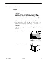
16-Bit 

ISA Expansion 

Card Slot

8-Bit 

ISA Expansion 

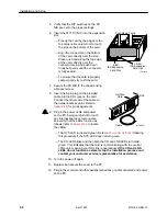
Card Slot

496-14968

Push Down Firmly

Installation and Setup

 2-8

5100-A2-GB21-10

April 1997

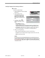
5. Verify that the DIP switches on the PC

NIC are set to the proper settings.

6. Insert the 5171 PC NIC into the expansion 

slot:

— Pick up the card by the edges or the 

top corners. Be careful not to touch 
the pins on the bottom of the card.

— Align the connector on the bottom 

of the card, directly over the slot. 
Place one hand along the top edge 
of the card, directly over the 
connector area, and push down 
firmly but gently until the connector 
is fully seated.

— To ensure that the card is properly

seated, gently try to lift the card.

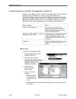
7. Secure the PC NIC to the chassis using 

a bracket screw.

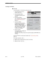
8. Insert the 6-pin plug on the provided 

cable into the DSL jack on the card. 
Connect the other end of the cable to 
the network access point. Refer to 

Appendix B 

for pin assignments.

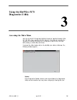
9. Plug in the power cable and power 

on the PC, being careful not to touch 
any internal boards or components,
and verify that the LEDs function as 
follows (refer to 

Appendix A 

to locate 

the LEDs):

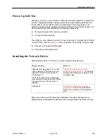
— The SYS LED turns solid green. Refer to 

Power-Up Self-Test

 following

this procedure if the SYS LED does not turn green.

— The CD LED blinks and then both the CD and LNK LEDs turn solid

green. This indicates that the card is communicating with the central
office unit, meaning your DSL link is operational. If the CD and LNK
LEDs do not function as stated, stop the installation process and
contact your customer service representative for assistance.

10. Turn the power off again.

11. Replace and secure the cover to the PC.

12. Plug in the monitor and other peripheral devices you disconnected and power

on the PC.

497-14971-01

DSL

HotWire

Card

Cable

Summary of Contents for HOTWIRE 5171

Page 1: ...HOTWIRE 5171 REMOTE PC NETWORK INTERFACE CARD USER S GUIDE Document No 5100 A2 GB21 10 April 1997...

Page 2: ...ves the right to revise this publication and to make changes from time to time in the contents hereof without obligation of Paradyne Corporation to notify any person of such revision or changes Change...

Page 3: ...ies to ensure compliance 4 In addition if the equipment is to be used with telecommunications circuits take the following precautions Never install telephone wiring during a lightning storm Never inst...

Page 4: ...llowing products Trade Name HOTWIRE Model Numbers 5171 B2 020 This device complies with Part 15 of the FCC Rules Operation is subject to the following two conditions 1 this device may not cause harmfu...

Page 5: ...Installation 2 1 Installing the HotWire 5171 Diagnostics Utility 2 2 Preparing the Card 2 2 Selecting an I O Base Address 2 3 Setting the I O Base Address 2 4 Setting the IRQ Switches 2 5 Inserting th...

Page 6: ...us 3 2 Viewing MAC Address 3 3 Resetting the Card 3 3 Checking Card Status 3 3 Checking Line Rate 3 3 Viewing Transmission Statistics and Network Status 3 4 Running Loopback Tests 3 5 Downloading Firm...

Page 7: ...r installing the 5171 PC NIC in the PC Chapter 2 Installation and Setup Describes how to install and set up the 5171 PC NIC Chapter 3 Using the HotWire 5171 Diagnostics Utility Describes how to use th...

Page 8: ...About This Guide iv 5100 A2 GB21 10 April 1997 Product Related Documents Document Number Document Title 5100 A2 GB20 HotWire 5100 DSL Access System Central Office Access Concentrator User s Guide...

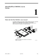
Page 9: ...ing Using the HotWire 5171 Remote PC NIC you can connect to a Central Office CO to access Internet service providers or corporate networks PC with Internal HotWire 5171 PC NIC PC with Internal HotWire...

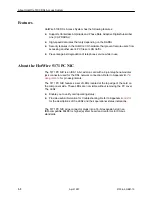
Page 10: ...C NIC The 5171 PC NIC is an ISA 16 bit add on card with a 6 pin telephone modular jack connector used for the DSL network connection Refer to Appendix B Pin Assignments for pin assignments The 5171 PC...

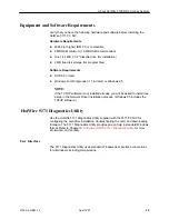
Page 11: ...NOTE If the TCP IP software is not installed already you will be asked to install it as a step in the Network Driver installation process Windows 95 includes the TCP IP software HotWire 5171 Diagnosti...

Page 12: ...Client PC HotWire Diagnostics Utility disk Cable HotWire 5171 Remote PC Network Interface Card User s Guide Order of Installation Install and set up your 5171 PC NIC by performing the following steps...

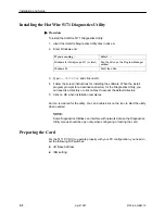
Page 13: ...alling the software When the install program prompts for a destination directory for the Diagnostics Utility you can specify a directory or click on Next to accept the default directory 5 Click on OK...

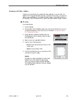
Page 14: ...ire program icon to access the main menu For a complete description of this menu refer to Chapter 3 Using the HotWire 5171 Diagnostics Utility 3 Select Recommend Base Address from the Configuration me...

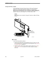
Page 15: ...80 NOTE Each hardware device included in the system must have a different I O base address 97 14998 01 LEDs DSL L N K C D R X T X T E S T S Y S 6 Pin Modular Jack DSL Connector 1 2 3 4 5 6 7 8 1 2 3 4...

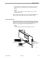
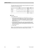
Page 16: ...tWire software is installed Setting the IRQ Switches IRQ hardware interrupt request is a signal used by your device to inform your CPU when it wants to transfer or receive data Use Switch Banks 2 and...

Page 17: ...able IRQ It not refer to your PC documentation for instructions on how to determine available IRQs Typically the available IRQ settings are 5 7 10 and 11 It is common in systems to use the other IRQs...

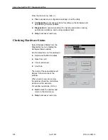
Page 18: ...application cards 1 Turn off the PC Disconnect cables for the monitor and any powered equipment to the PC Then lay the PC chassis on a flat surface 2 After waiting at least one minute remove the PC co...

Page 19: ...e into the DSL jack on the card Connect the other end of the cable to the network access point Refer to Appendix B for pin assignments 9 Plug in the power cable and power on the PC being careful not t...

Page 20: ...e test fails Recheck or change the IRQ setting Check the seating of the card Installing the Network Driver After installing the 5171 PC NIC you must install the network driver If you are using Refer t...

Page 21: ...em from the adapter menu and click on OK 8 Select Setup Verify the chosen base address and IRQ 9 Click on OK to return to the Drivers setup 10 Click on Close to end the Drivers setup 11 Click on OK to...

Page 22: ...rmined base address 10 Click on OK 11 The drivers will now be copied from a drivers to the hard drive Windows 95 may prompt you for some files needed to complete the TCP IP stack installation These ar...

Page 23: ...Recommend Base Address from the Configuration menu Typically if the software detects the 5171 PC NIC you will see only one base address listed in the Available Base Address window This address matche...

Page 24: ...tem when transferring or receiving data The default setting is 380 Interrupt No Signal used by your device to inform the CPU when the device wants to transfer or receive data The default setting is 5...

Page 25: ...rectory and you can use the following procedure to simply verify that the path is set appropriately Some other TCP IP package for example Chameleon Trumpet etc Locate the file in your file system and...

Page 26: ...ch package If you attempt to save but the file cannot be found or you need to change the path refer to Checking Setting Protocol ini Path for information Procedure To save the configuration settings 1...

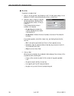
Page 27: ...s The window can be scrolled to provide the latest card status If the 5171 PC NIC is up and running the window displays the lines as shown in the example however the firmware version number may be dif...

Page 28: ...nflict 2 Attempt to Reset Card as described in Chapter 3 3 Recheck that IRQ settings on card match software Cannot connect to Central Office IRQ conflict Network Link is Down Network cable is not conn...

Page 29: ...DSL network This utility also provides the capability to download firmware and run diagnostic tests on the card when instructed by a central office technician To access the utility double click on th...

Page 30: ...cs and running loopback tests Help to access screen help Checking Hardware Status Select Hardware Status from the Diagnostics menu to display the Hardware Status window Use the selections on this wind...

Page 31: ...tatus The reset operation performs a power up self test on the card as described in Chapter 2 Checking Card Status Click on Card Status to interpret the operational status of the card This selection a...

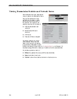
Page 32: ...of Packets transmitted and received Bytes transmitted and received CRC errors Packets or frames dropped Link State indicates the status of thenetwork When the Link State is Up the DSL connection is o...

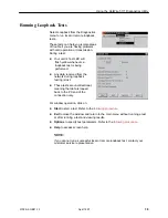
Page 33: ...med Any data received from the network during loopback testing is lost These tests are uni directional meaning that data is looped back to the PC end of the connection only For window operation click...

Page 34: ...The default is 10 Packet Size to indicate the size of packets to be tested The default is 64 bytes For window operation select the values to be used during the test and or click on OK to accept the p...

Page 35: ...he Diagnostic Utility main menu The Open window appears This window uses standard Windows user interface conventions 2 Select the appropriate drive for example drive a as shown on the sample Open wind...

Page 36: ...ing illustration shows the location of the LEDs on the faceplate The table interprets the status of the card when the LEDs are on off or blinking 97 15015 01 1 2 3 4 5 6 7 8 1 2 3 4 5 6 7 8 1 2 3 4 TE...

Page 37: ...nking On Off Normal operation Indicates presence of DSL traffic No data being sent System TEST Steady Blinking Blinking On Off In download mode In loopback mode Normal operation SYS Off On Error condi...

Page 38: ...Assignments B The following table defines the pinouts for the DSL connector It is a 6 pin non keyed modular jack female connector Table B 1 DSL Connector Pin Assignments Pin Use 1 NC 2 NC 3 RING 4 TIP...

Page 39: ...Carrierless Amplitude and Phase Modulation RADSL multi speed interface to the local loop Digital Interface PC ISA bus and NDIS 2 01 3 0 compliant IP protocol stack Management The 5171 PC NIC supports...

Page 40: ...ff Off Off Off 0x210 On Off Off Off Off On 0x220 On Off Off Off On Off 0x230 On Off Off Off On On 0x240 On Off Off On Off Off 0x250 On Off Off On Off On 0x260 On Off Off On On Off 0x270 On Off Off On...

Page 41: ...2 Switch 1 0x320 On On Off Off On Off 0x330 On On Off Off On On 0x340 On On Off On Off Off 0x350 On On Off On Off On 0x360 On On Off On On Off 0x370 On On Off On On On 0x380 On On On Off Off Off 0x39...

Page 42: ...receiving data Hardware Interrupt Request A signal used by your device to inform your CPU when it wants to transfer or receive data Local Area Network A network that spans a small geographic area e g...

Page 43: ...3 1 Digital Interface C 1 Digital Subscriber Line iii DIP Switch on off position 2 5 SW1 2 4 SW2 2 5 SW3 2 5 Switches 7 8 2 5 Disk requirements 1 3 storage 1 3 F File Menu 3 2 Exit 3 7 Save 2 15 Firmw...

Page 44: ...M Requirements 1 3 Recommend Base Address 2 12 window 2 3 Remote Loopback Test 2 17 3 5 failed 3 5 failed during installation 2 17 running 3 5 setting options 3 6 window 3 5 Reset Card 3 3 S Saving co...

Reviews: