


MTU-M Installation Procedures
2-2
7900-A2-GB20-00
March 1998
"
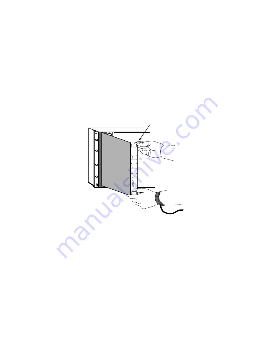
Procedure
To install the MTU-M:
NOTE:
A maximum of four Hotwire Model 7900 nests can be installed into one
standard 72-inch equipment rack. If more than one nest is installed in the
same equipment rack, install the MTU-M in slot 1 of the top nest. The nest
containing the MTU-M is referred to as the primary nest.
1. Remove the MTU-M from any protective packaging.
2. Align the circuit board with the top and bottom card guides of Slot 1.
NETWORK
LOS/AIS/BER
LOCAL
REMOTE
REMOTE
LOOP BK
SYSTEM
POWER
FAIL
SDSL
LOS / BER
LOOP
OK
FAIL
SELECT
NEXT
ALARMS
MAJOR
MINOR
ABNORM
ACO
ACTIVE
97-15598
MTU-M Slot 1
MTU-M
POWER
FAIL
NMS LINK
MODEMS
ALARMS
MAJOR
MINOR
ABNML
ACO
ACTIVE
C
O
N
S
O
L
E
RESET
3. Slide the MTU-M into the slot until the backplane connector plug is seated
firmly into the backplane.
4. Tighten the retaining screws at the top and bottom of the MTU-M front panel.
Summary of Contents for HOTWIRE 7900
Page 8: ...Contents iv 7900 A2 GB20 00 March 1998 This page intentionally left blank ...
Page 28: ...System Terminal Interface 4 6 7900 A2 GB20 00 March 1998 This page intentionally left blank ...
Page 72: ...Testing 9 12 7900 A2 GB20 00 March 1998 This page intentionally left blank ...
Page 82: ...Glossary GL 4 7900 A2 GB20 00 March 1998 This page intentionally left blank ...


