


MTU-M Installation Procedures
2-3
7900-A2-GB20-00
March 1998
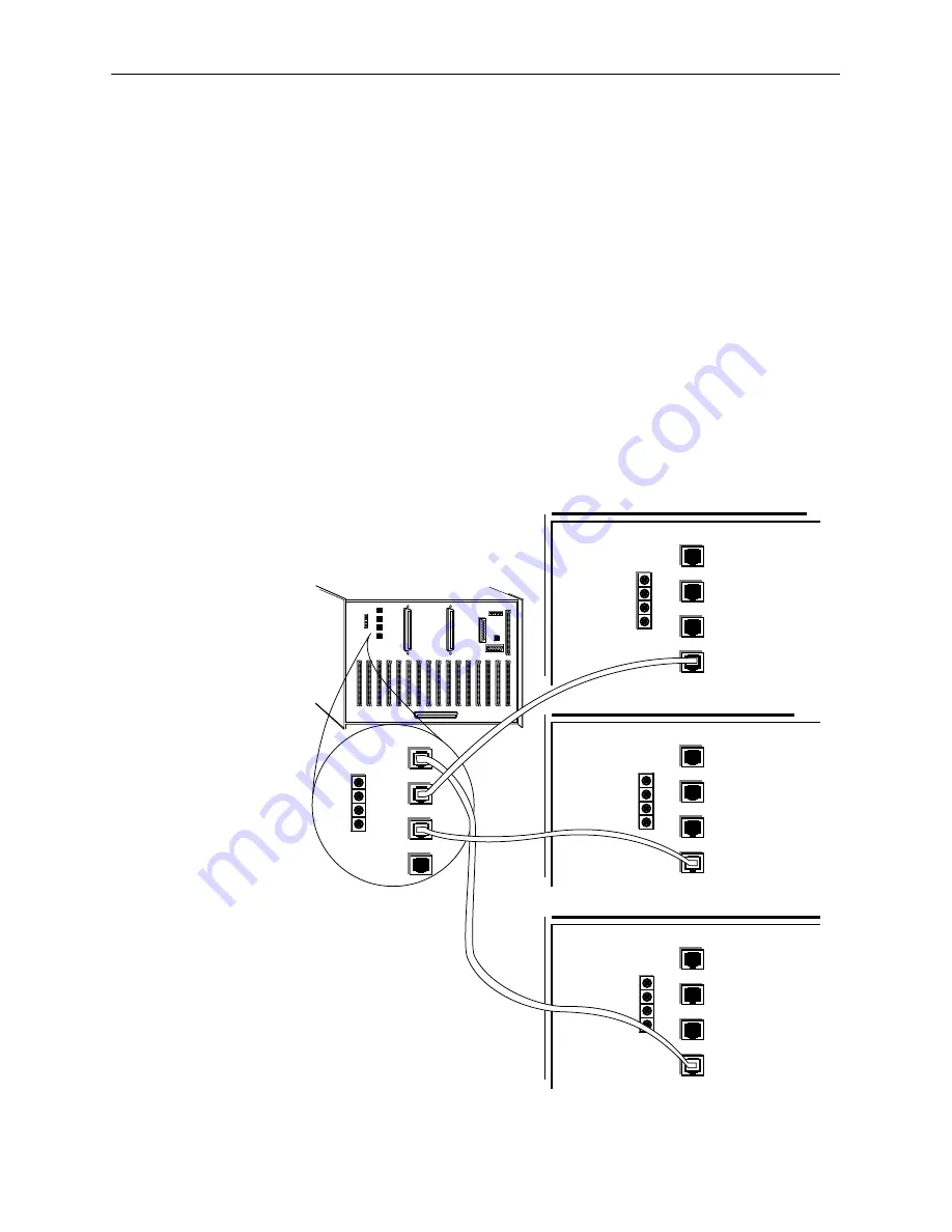
Connecting the Primary Nest to Additional Nests
Connections between nests are only made from the primary nest (Nest 1) to each
expansion nest (Nests 2, 3, and 4). Connecting the primary nest to an expansion
nest allows the MTU-M to monitor the nest card termination units in Nests 2, 3,
and 4.
"
Procedure
To connect the primary nest to each expansion nest:
1. Connect the primary nest and Nest 2 by connecting the nest expansion cable
between J28 (TO 2) on the primary nest to J26 (FROM 1) on Nest 2.
2. Connect the primary nest and Nest 3 by connecting the nest expansion cable
between J29 (TO 3) on the primary nest to J26 (FROM 1) on Nest 3.
3. Connect the primary nest and Nest 4 by connecting the nest expansion cable
between J27 (TO 4) on the primary nest to J26 (FROM 1) on Nest 4.
97-15414
TO 4
TO 2
TO 3
FROM 1
POWER
Bgnd
–48vB
Agnd
–48vA
TO 4
TO 2
TO 3
FROM 1
POWER J27
–48vB
Agnd
–48vA
P6
P5
Alarms
RS232
Modem
DB25
Network
Management
10BaseT
AUI
DB15
Local Loop
Nest 1
(Primary)
Nest 2
TO 4
TO 2
TO 3
FROM 1
POWER
Bgnd
–48vB
Agnd
–48vA
TO 4
TO 2
TO 3
FROM 1
POWER
Bgnd
–48vB
Agnd
–48vA
TO 4
TO 2
TO 3
FROM 1
POWER
Bgnd
–48vB
Agnd
–48vA
Nest 3
Nest 4
J27
J28
J29
J26
J28
J29
J26
J27
J28
J29
J26
J27
J28
J29
J26
J27
J28
J29
J26
Summary of Contents for HOTWIRE 7900
Page 8: ...Contents iv 7900 A2 GB20 00 March 1998 This page intentionally left blank ...
Page 28: ...System Terminal Interface 4 6 7900 A2 GB20 00 March 1998 This page intentionally left blank ...
Page 72: ...Testing 9 12 7900 A2 GB20 00 March 1998 This page intentionally left blank ...
Page 82: ...Glossary GL 4 7900 A2 GB20 00 March 1998 This page intentionally left blank ...


