background image

2. Using the Asynchronous Terminal Interface

2-8


 September 2004

7990-A2-GB20-20

Switching Between Screen Work Areas

Select Ctrl-a to switch between the two screen work areas to perform all screen 
functions.

Procedure


To access the screen function area below the dotted line:

1. Press Ctrl-a to switch from the screen area to the function key and message 

area below the dotted line.

2. Select either the function’s designated (underlined) character or press the Tab 

key until you reach the desired function key.

Example:

To save the current screen, type 

or 

S

 (Save).

3. Press Enter.

4. To return to the screen area above the dotted line, press Ctrl-a again.

Ending an ATI Session

Use the Exit function key from any screen to terminate the session.

Procedure


To end a session with the asynchronous terminal interface:

1. Press Ctrl-a to go to the function key and message area below the dotted line.

2. Save changes if required. A confirmation message appears if you have made 

but not saved changes to your configuration.

3. Tab to Exit  (or type 

e

 or 

E

) and press Enter.

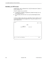
m

ain/config/dsl_interface                                                      

                                                                     Model: 799x

                            DSL INTERFACE OPTIONS

                      Estimated Line Length:            Long

                      Startup Margin:                   0dB

                      Max DSL Rate:                     2056   Kbps

                      Min DSL Rate:                     2056   Kbps

                      EIA-530 Payload Rate:             2048   Kbps

                      Remotely Initiated Loopback:      Enable

                      Peer IP Address:                  135.090.025.001  Clear

   Circuit Identifier:                                                  Clear


--------------------------------------------------------------------------------

Ctrl-a to access these functions, ESC for previous menu      MainMenu    Exit

 Save

Summary of Contents for Hotwire 7995

Page 1: ...Hotwire TDM SHDSL Endpoints Models 7995 A2 411 7995 A2 421 7995 A2 422 7995 A2 700 7996 A2 410 7996 A2 420 and 7996 A2 700 User s Guide Document No 7990 A2 GB20 20 September 2004...

Page 2: ...ocumentation training distributor locations or Paradyne worldwide office locations use one of the following methods Internet Visit the Paradyne World Wide Web site at www paradyne com Be sure to regis...

Page 3: ...Capabilities 1 6 Management Information Base MIB Support 1 6 SNMP Trap Support 1 7 2 Using the Asynchronous Terminal Interface User Interface Access 2 1 Communication Port Settings 2 1 Initiating an A...

Page 4: ...iguring the Unit Using the Internal Switches Overview 4 1 Configuring the Unit Using Internal Switches 4 2 Switchpack Location 4 3 Model 7995 Switchpack Definitions 4 4 Model 7996 Switchpack Definitio...

Page 5: ...5 Remote Send Line Loopback 7 6 Send and Monitor 511 Pattern 7 7 SYNC Data Port Tests Model 7995 7 8 Data Terminal Loopback 7 9 Data Channel Loopback 7 10 Repeater Loopback 7 11 Send Remote Data Chann...

Page 6: ...kUp and linkDown B 3 Enterprise Specific Traps B 5 C Connectors Cables and Pin Assignments Overview C 1 Power Input Connector C 2 COM Port Connector C 2 COM Port to PC Cable C 3 COM Port to LAN Adapte...

Page 7: ...al Startup and Configuration Provides procedures for setting up the user interface and for configuring the unit using the asynchronous terminal interface Chapter 4 Configuring the Unit Using the Inter...

Page 8: ...727 530 2000 Appendix C Connectors Cables and Pin Assignments Contains connector and interface information Appendix D Technical Specifications Contains physical and regulatory specifications network...

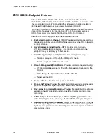
Page 9: ...the highest line rate that the 2 wire loop supports then automatically configures the unit to the highest multiple of 64 kbps supported by that line rate Thirty one line rates are available At all rat...

Page 10: ...nt locally or remotely by Telnet session Local Management endpoint Provides local management using a Terminal or equivalent through the COM port of the unit Telnet through the COM port of the unit Rem...

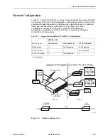
Page 11: ...upported standalone to standalone configurations are shown in Table 1 1 Supported Standalone STU R STU C Combinations Figure 1 1 Sample Configurations Table 1 1 Supported Standalone STU R STU C Combin...

Page 12: ...mation about the front panel LEDs refer to Front Panel LEDs in Chapter 6 Monitoring and Troubleshooting Figure 1 2 Hotwire 7995 TDM SHDSL Endpoint with Synchronous Interface Front Panel Figure 1 3 Hot...

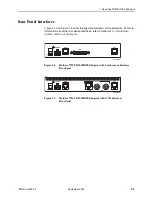
Page 13: ...ints For more information about the rear panel interfaces refer to Appendix C Connectors Cables and Pin Assignments Figure 1 4 Hotwire 7995 TDM SHDSL Endpoint with Synchronous Interface Rear Panel Fig...

Page 14: ...13 and RFC 2863 was 1573 Defines the general objects for use with a network management protocol in TCP IP internets and provides general information about the unit MIB II is backward compatible with M...

Page 15: ...er IP Address Assignment 01 17057 DSLAM Network 799x AC INPUT AC 48VDC CLASS 2 OR LIMITED PWR SOURCE RTN 48V A A B B T5A 2 4 6 A B 3 1 2 POSITION STACK ALM A IN B DC FUSES T4A MIN 48V 5 DC PWR FAN OUT...

Page 16: ...1 About the TDM SHDSL Endpoint 1 8 September 2004 7990 A2 GB20 20...

Page 17: ...al port of the DSLAM management card Telnet session through the Embedded Operations Channel EOC NOTE Only one terminal interface session can be active at a time and another user s session cannot be fo...

Page 18: ...ou will see A connection refused or connection failed message if you are using a Telnet session or The IP address of the other user if you are using the Management Serial port If security is enabled o...

Page 19: ...ow your unit is currently configured Effective security access level An access level that is typically set by the system administrator for each interface and each user Data selection criteria What you...

Page 20: ...g Configuration Loader Current Configuration Edit Display System Options Communication Port Management and Communication Change Identity Administer Logins Download Code Apply Download Reset Device Dev...

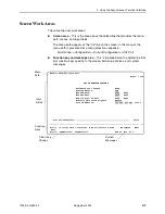
Page 21: ...y and message area This is the area below the dotted line that lists function keys specific to the screen field value choices and system messages main config dsl_interface Model 799x DSL INTERFACE OPT...

Page 22: ...o the left Ctrl l Redraw the screen display clearing information typed in but not yet entered Delete Del Delete character that the cursor is on Down Arrow or Ctrl d Move cursor down one field within a...

Page 23: ...ng the designated function key If a field is blank and the Field Values screen area displays valid selections press the spacebar The first valid value for the field will appear Continue pressing the s...

Page 24: ...a above the dotted line press Ctrl a again Ending an ATI Session Use the Exit function key from any screen to terminate the session Procedure To end a session with the asynchronous terminal interface...

Page 25: ...ge 3 2 Connecting to the Network on page 3 3 Connecting to a DTE on page 3 3 Connecting to a System Terminal on page 3 4 Entering Identity Information on page 3 5 Choosing a Configuration Method on pa...

Page 26: ...DM SHDSL unit is capable of operating on a 24 or 48 VDC power supply CAUTION Make sure that the power switch is set to off before connecting the power cable Procedure To use the DC power cable with 24...

Page 27: ...to model See Appendix C Connectors Cables and Pin Assignments for more information Table 3 1 Power Input Connector Pin Number Wire Color Signal 1 Black 48 VDC Return 2 Red 48 VDC Return 3 Green Groun...

Page 28: ...be a VT100 compatible terminal or a PC running terminal emulation software Procedure To connect the unit to a system terminal 1 Connect the 9 pin end of the terminal cable into a COM port on your PC...

Page 29: ...entry fields are System Name The general SNMP system name System Location The physical location of the SNMP managed device System Contact Identification information such as contact name phone number...

Page 30: ...ible for the unit 4 Press Ctrl a to switch to the function key and message area below the dotted line 5 Select Save and press Enter See Viewing Identity Information in Chapter 6 Monitoring and Trouble...

Page 31: ...ory Configuration area You can find default information by Referring to Appendix A Configuration Options Accessing the Configuration branch of the TDM SHDSL endpoint s menu The TDM SHDSL endpoint has...

Page 32: ...ing Enter If you select Then Current Configuration The selected configuration option set is loaded and the Configuration Edit Display menu screen appears Configuration Loader The Configuration Loader...

Page 33: ...his menu selection sequence Main Menu Configuration Current Configuration or Main Menu Configuration Default Factory Configuration In the menu selection sequences contained in this manual Current Conf...

Page 34: ...Synchronous Data Port Options Model 7995 Table A 4 G 703 Interface Options Model 7996 Table A 5 Synchronous DTE interface Model 7995 G 703 interface Model 7996 System Options System Options Table A 6...

Page 35: ...to three characters The system will automatically upload the configuration file and create directories and filenames as needed UNIX machine If your server is hosted by a UNIX machine the configuration...

Page 36: ...on is the COM port if COM port is set to NetLink see Table A 7 Communication Port Options in Appendix A Configuration Options 4 Position the cursor in the TFTP Transfer Direction field Use the spaceba...

Page 37: ...s selected before Save or Save has been selected from any menu in the Configuration Edit branch a Save Configuration screen appears requiring a Yes or No response If the DSL Mode configuration option...

Page 38: ...the Device If the user interface is functional you can perform a power on reset of the unit from the Control menu Procedure To reset the unit from the Control menu 1 Follow this menu selection sequen...

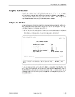
Page 39: ...U C To access the DSL Interface Options screen follow this menu selection sequence Main Menu Configuration Current Configuration DSL Port To enable Adaptive Rate set the Min DSL Rate to a value lower...

Page 40: ...ress or the MCP IP address for the MCP FFS 3 Position the cursor in the TFTP Server Destination field Use the spacebar to select a network destination for the TFTP server Select DSL if the TFTP server...

Page 41: ...aded firmware 1 Press the Escape key to return to the Control menu Select Apply Download 2 On the Apply Download screen type Yes to reset the card and activate the code Selecting Yes causes the TDM SH...

Page 42: ...3 Initial Startup and Configuration 3 18 September 2004 7990 A2 GB20 20...

Page 43: ...compatible terminal and the unit s Configuration menus or by manually changing switches on the board The unit is shipped with the switchpack disabled to allow settings to be made through the Configur...

Page 44: ...your nearest sales or service representative Procedure To configure the unit using internal Switchpack S3 1 Power off the unit 2 Remove the enclosure cover Use a Phillips screwdriver to remove the two...

Page 45: ...0 September 2004 4 3 Switchpack Location To locate Switchpack S3 refer to Figure 4 1 Hotwire TDM SHDSL Endpoint Switchpack Location Figure 4 1 Hotwire TDM SHDSL Endpoint Switchpack Location Switchpack...

Page 46: ...ne rates If Auto Rate is enabled DSL Line Rate represents the Auto Rate ceiling Valid only for a unit configured as an STU C All OFF 2056 kbps 6 Enable or disable Switchpack S3 OFF Switchpack Disabled...

Page 47: ...e rates If Auto Rate is enabled DSL Line Rate represents the AutoRate ceiling Valid only for a unit configured as an STU C All OFF 2056 kbps 6 Enable or disable Switchpack S3 OFF Switchpack Disabled O...

Page 48: ...4 Configuring the Unit Using the Internal Switches 4 6 September 2004 7990 A2 GB20 20...

Page 49: ...gin Required option Enable the COM port Login Required option Limit access by setting a Session Access Level option of Operator for the Telnet session Limit access by setting a Session Access Level op...

Page 50: ...ons When access is through Telnet and a login is required for a Telnet session the effective access level is the more restrictive of the Telnet session access level or the login access level See Table...

Page 51: ...e Main Menu Control Administer Logins 2 Select New and press Enter The Login Entry screen appears main control admin_logins Model 799x ADMINISTER LOGINS Page 1 of x Login ID newuser Password Access Le...

Page 52: ...ord follow this menu selection sequence Main Menu Control Administer Logins 2 Select PgUp or PgDn and press Enter to page through login pages records until you find the one to be deleted 3 Once the co...

Page 53: ...s COM port configure the terminal to operate at 9 6 kbps using a character length of 8 bits with one stop bit and no parity 2 Reset the unit then immediately and repeatedly press Enter at a rate of at...

Page 54: ...anagement Assign the SNMP community names of the SNMP Managers that are allowed to access the unit s Management Information Base MIB Specify Read or Read Write access for each SNMP community name Limi...

Page 55: ...h and Status Messages Self Test Results Messages Test Status Messages Entry Response Messages on page 6 8 Viewing DSL Error Statistics on page 6 10 Viewing DSL Performance Statistics on page 6 12 View...

Page 56: ...plays messages in priority order highest to lowest Refer to Table 6 1 Health and Status Messages Self Test Results Results of the Diagnostic test run on the device itself Refer to Table 6 2 Self Test...

Page 57: ...terface has fallen below the configured threshold 1 Reconfigure the unit to a lower DSL Attenuation Threshold 2 Contact network provider DSL CRC Threshold The number of counted CRCs for the DSL interf...

Page 58: ...that the network cable is securely attached at both ends 2 Verify proper STU C and STU R configuration 3 Contact network provider Net Com Link Down The Network communication link is down Communicatio...

Page 59: ...C is configured for TS16 signaling Voice mode and the STU R is not configured to support TS16 signaling 1 Verify endpoint is a G 703 product EIA 530 A products do not support signaling 2 Replace endp...

Page 60: ...it and try again 2 Call your service representative for assistance Device Failed One or more of the unit s integrated circuit chips failed device level testing 1 Reset the unit and try again 2 Call yo...

Page 61: ...st is active DLB Test Active A DTE Loopback test is active DTLB Test Active A Data Terminal Loopback test is active Lamp Test Active The Lamp Test is active causing the LEDs on the front panel to ligh...

Page 62: ...n IDs Command Complete Action requested has successfully completed No action is needed Invalid Character A nonprintable ASCII character has been entered Reenter the information using valid characters...

Page 63: ...rd Matching Error Re enter Password Password entered in the Reenter Password field of the Administer Logins screen does not match what was entered in the Password field Try again Please Wait Command t...

Page 64: ...mance dsl_error Model 799x DSL ERROR STATISTICS Current Interval Timer 002 ES SES UAS LOSW Near Far Near Far Near Far Near Far Current Int 000 000 000 000 000 000 000 000 Interval 01 000 000 000 000 0...

Page 65: ...ord Seconds Seconds during which the SHDSL line had a Loss of Sync Word defect Maximum value is 900 Use the virtual function keys to page through the intervals and clear statistics This Field Contains...

Page 66: ...Statistics follow this menu selection sequence Main Menu Status Performance Statistics DSL Performance Statistics Select PgUp or PgDn to view more statistics main status performance dsl_perf Model 79...

Page 67: ...Use the virtual function keys to page through the intervals and clear statistics This Field Contains Current Interval Timer The number of seconds which have elapsed in the current 15 minute interval...

Page 68: ...cleared at the start of 10 seconds with no SES Maximum value is 900 SES Severely Errored Seconds Seconds during which 805 or more CRC errors more than 16 Frame Alignment Signal FAS errors or at least...

Page 69: ...t error detected V Line code violation detected None No significant events have occurred Use the virtual function keys to page through the intervals and clear statistics This Field Contains Current In...

Page 70: ...he SNR reference is the value needed to maintain a bit error rate of 10 7 Attenuation The number of dB that the signal has fallen below a reference point Tx Power The transmit power level The followin...

Page 71: ...0 LOSWS Loss Of Sync Word Seconds Seconds during which the SHDSL line had a Loss of Sync Word defect Maximum value is 900 Fields on this screen include Field Contains Current Interval Timer The number...

Page 72: ...D provides the status of the DTE interface The DSL Loop LED displays the activity on the DSL interface To view the Display LEDs status screen follow this menu selection sequence Main Menu Status Displ...

Page 73: ...ng Normal operation No power to the unit Unit is in minimum mode and a download is required ALARM Red On Off Device failure or self test has failed Self test passed TEST Yellow On Off Slow Cycling Loo...

Page 74: ...ayed in the Identity screen is stored in the device Model Number The 9 character model number of the device representing the product family model and feature Serial Number The 7 digit serial number of...

Page 75: ...ion Refer to Table 6 1 Health and Status Messages for a recommended action An LED is not lit that should be lit LED is burned out Use Table 6 5 Front Panel LEDs to determine the correct behavior of th...

Page 76: ...eiving data The network or data port cables are not connected check front panel LEDs for more information Check network and data port cables Run loopback tests Refer to Chapter 7 Testing A test is bei...

Page 77: ...port tests to start and stop tests on the Sync port interface Model 7995 only Send and monitor 511 pattern tests Device tests to start and stop the lamp test You can also use the Test menu to abort a...

Page 78: ...opback Down Send Inactive 00 00 00 Network Pattern Tests Send and Monitor 511 Stop Active hh mm ss Errors 99999 Ctrl a to access these functions ESC for previous menu MainMenu Exit ResetMon main test...

Page 79: ...attempt is made to start the test DSL Line Loopback A DSL Line Loopback loops the received signal on the DSL port back to the DSL port without change Procedure To run a DSL Line Loopback 1 Position t...

Page 80: ...Repeater Loopback 1 Position the cursor at the Start command next to G 703 Repeater Loopback on the DSL G 703 Tests screen 2 Press Enter The Start command is changed to Stop 3 To manually stop the te...

Page 81: ...s active Procedure To run a G 703 DTE Loopback 1 Position the cursor at the Start command next to G 703 DTE Loopback on the DSL G 703 Tests screen 2 Press Enter The Start command is changed to Stop 3...

Page 82: ...un a Remote Send Line Loopback 1 Position the cursor at the Up or Down selection next to Send Line Loopback on the DSL Tests or DSL G 703 Tests screen 2 Press the spacebar to select either Up or Down...

Page 83: ...d monitors a 511 pattern Activating the Send and Monitor 511 Pattern test causes the EOC used for management to be lost to the remote unit Procedure To run a Send and Monitor 511 test 1 Allow the mode...

Page 84: ...Use the Command column to start or stop a test When the Status column shows that a test is Inactive Start is displayed when a test is Active Stop is displayed Position the cursor at the desired Start...

Page 85: ...ition the cursor at the Start command next to Data Terminal Loopback on the SYNC Data Port Tests screen 2 Press Enter The Start command is changed to Stop 3 To manually stop the test verify that the c...

Page 86: ...the cursor at the Start command next to Data Channel Loopback on the SYNC Data Port Tests screen 2 Press Enter The Start command is changed to Stop 3 To manually stop the test verify that the cursor i...

Page 87: ...Loopback 1 Position the cursor at the Start command next to Repeater Loopback on the SYNC Data Port Tests screen 2 Press Enter The Start command is changed to Stop 3 To manually stop the test verify t...

Page 88: ...screen 2 Press the spacebar to select the desired code Up or Down 3 Position the cursor at the Start command next to Send Remote DCLB on the SYNC Data Port Tests screen 4 Press Enter The Status field...

Page 89: ...edure To test the LEDs 1 Position the cursor at the Start command next to Lamp Test on the Device Tests screen 2 Press Enter The Start command is changed to Stop During the Lamp Test all LEDs blink si...

Page 90: ...A 6 System Options in Appendix A Configuration Options Command column Under the Command column on any test screen position the cursor at Stop next to the active test and press Enter to stop a specifi...

Page 91: ...7 Testing 7990 A2 GB20 20 September 2004 7 15...

Page 92: ...7 Testing 7 16 September 2004 7990 A2 GB20 20...

Page 93: ...unit DSL Port Threshold Traps DSL Port Threshold Trap Options Table A 3 Threshold traps for the DSL port on the unit SYNC Port or G 703 Synchronous Data Port Options Model 7995 Table A 4 G 703 Interf...

Page 94: ...STU C and Spectrum Management is enabled see Table A 6 System Options Short Can support speeds up to 2056 kbps in 64 kbps increments Medium Can support speeds up to 1480 kbps in 64 kbps increments Lon...

Page 95: ...30 A interface the Payload Rate set on the STU C determines the port speed of the synchronous port of the STU R Only 64 and 128 kbps are selectable otherwise this field is read only See Table A 2 G 70...

Page 96: ...ld Clear Default Setting blank Uniquely identifies the circuit number of the transmission vendor s DSL line for troubleshooting purposes ASCII text field Enter a maximum of 128 characters All printabl...

Page 97: ...6 520 448 7 584 512 8 648 576 9 712 640 10 776 704 11 840 768 12 904 832 13 968 896 14 1032 960 15 1096 1024 16 1160 1088 17 1224 1152 18 1288 1216 19 1352 1280 20 1416 1344 21 1480 1408 22 1544 1472...

Page 98: ...n Menu Configuration Current Configuration DSL Port Threshold Traps NOTE DSL Port Threshold Traps appears only when DSL Mode is set to STU C see Table A 6 System Options main config dsl_trap Model 799...

Page 99: ...n a 15 minute interval after which a trap will be sent LOSW Trap Threshold Possible Settings 1 900 or 0 to Disable Default Setting 0 Specifies the threshold for Loss of Sync Word Seconds events in a 1...

Page 100: ...patible DTE can be connected using an MS34 to DB25 adapter cable to connect to the DB25 Port connector on the rear panel of the unit RS449 The port is configured as an RS 449 compatible DCE An RS 449...

Page 101: ...U C or an external clock provided by the DTE connected to the synchronous data port Transmit Clock Source appears only when DSL Mode is set to STU C see Table A 6 System Options and the device is in F...

Page 102: ...alt None Default Setting Halt Specifies the action taken on the synchronous data port when an LOS Loss Of Signal alarm is received on the DSL interface Halt Stops the transmission of data on the data...

Page 103: ...ed to this port to the DTE attached to this port This loopback is controlled by the Remote Loopback interchange circuit RL CCITT 140 The far end equipment must support in band V 54 loopbacks Both Give...

Page 104: ...Mode is set to STU C see Table A 6 System Options and the DSL line rate is 2056 kbps Framed The unit conforms to G 704 framing Unframed G 704 framing is disabled Line Coding Possible Settings AMI HDB...

Page 105: ...sed for voice or data Signaling Time slot 16 is used for signaling the unit is in voice mode Data Time slot 16 is used for data the unit is in data mode Send AIS on Network Failure Possible Settings E...

Page 106: ...is configured as a SHDSL Transceiver Unit Central Site An STU C is typically found at the central office The STU C polls the STU R and controls the system startup procedure the timing of the loop and...

Page 107: ...r a test to be active before automatically ending Test Duration min appears only when Test Timeout is enabled 1 120 Amount of time in minutes a test runs before terminating G 703 Line Termination Mode...

Page 108: ...the United Kingdom it is a requirement that the product comply with the OFTel PSD mask for the loop length requested short medium or long Support for this requirement is provided by enabling Spectrum...

Page 109: ...reen appears main config com Model 799x COMMUNICATION PORT OPTIONS Port Use Terminal Port Type Asynchronous Data Rate 9 6 Character Length 8 Parity None Stop Bits 1 Ignore Control Leads Enable Login R...

Page 110: ...for asynchronous communication Synchronous Configures the communication port for synchronous communication Data Rate Possible Settings 9 6 14 4 19 2 28 8 38 4 57 6 115 2 Default Setting 9 6 Specifies...

Page 111: ...created with a password and access level Refer to Creating a Login in Chapter 5 Security Login Required appears only when Port Use is set to Terminal Enable Login ID and password are required to acce...

Page 112: ...matically after the Disconnect Time Disable A terminal session is never closed due to inactivity Disconnect Time Minutes Possible Settings 1 60 Default Setting 5 Number of minutes of inactivity before...

Page 113: ...these options determine what level of security to apply to the session to control access Only one Telnet session is allowed at a time Initial values are determined by the configuration you currently h...

Page 114: ...t session access level is interrelated with the access level of the Login ID Refer to ATI Access Levels in Chapter 5 Security for more information Administrator This is the higher access level permitt...

Page 115: ...he Communication Protocol Options screen follow this menu selection sequence Main Menu Configuration Current Configuration Management and Communication Communication Protocol main config management co...

Page 116: ...estination Possible Settings None COM DSL Default Setting None Specifies where the default management network is connected For example if your default network is connected to the COM port select COM a...

Page 117: ...mask are used 000 000 000 000 255 255 255 255 Enter an address for the Communication Port Subnet Mask Clear Clears the mask to all zeros Communication Port Link Protocol Possible Settings PPP SLIP Def...

Page 118: ...sequence Main Menu Configuration Current Configuration Management and Communication General SNMP Management main config management SNMP Model 799x GENERAL SNMP MANAGEMENT OPTIONS SNMP Management Enabl...

Page 119: ...omplex systems only Name 1 Access Possible Settings Read Read Write Default Setting Read Write Determines the access level for Community Name 1 Read Allows read only access get for Community Name 1 Re...

Page 120: ...ddress 135 014 040 001 Clear Access Type Read Write NMS 2 IP Address 135 014 003 027 Clear Access Type Read Write NMS 3 IP Address 135 014 001 008 Clear Access Type Read NMS 4 IP Address 135 014 002 0...

Page 121: ...5 Clear Default Setting 000 000 000 000 Specifies the Internet Protocol address used to identify each SNMP manager limit of 10 001 000 000 000 223 255 255 255 Enter an address for each SNMP manager Th...

Page 122: ...ction sequence Main Menu Configuration Current Configuration Management and Communication SNMP Traps main config management trap Model 799x SNMP TRAPS OPTIONS SNMP Traps Enable NMS 1 IP Address 135 01...

Page 123: ...irst byte is 001 to 223 with the exception of 127 The range for the remaining three bytes is 000 to 255 Clear Clears the IP address and sets to all zeros NMS n Destination Possible Settings DSL COM De...

Page 124: ...the communication interfaces is operational Down A linkDown trap is generated when the unit recognizes a failure in one of the communication interfaces Both Sends trap messages for detection of both l...

Page 125: ...x Variable Binding The ifIndex values shown in Table B 1 IfIndex Values are supported for Hotwire 7995 7996 TDM SHDSL Endpoints For a unit defined as an STU R in an IP Conservative configuration all t...

Page 126: ...and stabilizes There are no variable bindings Reset command Power disruption Table B 3 authenticationFailure Trap SNMP Trap Description Possible Cause authenticationFailure Failed attempts to access...

Page 127: ...supported are 1 COM Port 2 DSL Network Interface 6 G 703 Port 10 EIA 530 A Port ifAdminStatus RFC 2863 This object specifies the operational state of the interface up 1 The interface is enabled down 2...

Page 128: ...e1 19 Used for G 703 interface propPointToPointSerial 22 Used for EOC ppp 23 Used for the COM Port when configured for PPP slip 28 Used for the COM Port when configured for SLIP rs232 33 Used for the...

Page 129: ...n Variable bindings devSelfTestResults Failure of one or more of the unit s hardware components enterpriseDevice Fail 3 An internal device failure No variable bindings Operating software has detected...

Page 130: ...iseTestStart Stop variable bindings Possible Cause DSL Network ifIndex RFC 2863 ifAdminStatus RFC 2863 ifOperStatus RFC 2863 ifType RFC 2863 ifTestType RFC 2863 The following objects control tests in...

Page 131: ...863 ifOperStatus RFC 2863 ifType RFC 2863 ifTestType RFC 2863 The following objects control tests in SNMP managed devices noTest 0 Stops the test in progress testLoopDCLB 3 Initiates a Data Channel Lo...

Page 132: ...B Standards Compliance for SNMP Traps B 8 September 2004 7990 A2 GB20 20...

Page 133: ...ector on page C 2 COM Port Connector on page C 2 COM Port to PC Cable on page C 3 COM Port to LAN Adapter Cable on page C 4 G 703 Network Interface on page C 5 EIA 530 A Port on page C 6 EIA 530 A to...

Page 134: ...t Connector J6 The data signals on this port are referenced to a DTE interface Table C 1 Power Input Connector Pin Number Wire Color Signal 1 Black 48 Vdc Return 2 Red 48 Vdc Return 3 Green Ground 4 W...

Page 135: ...14 foot 26 AWG 8 conductor cable with an 8 position unkeyed modular connector and a DB9 socket connector See Figure C 1 COM Port to PC Cable Feature Number 3100 F2 550 Figure C 1 COM Port to PC Cable...

Page 136: ...dapter cable is a 14 foot 24 AWG 6 conductor cable with an 8 position unkeyed modular connector at either end See Figure C 2 COM Port to PC Cable Feature Number 3100 F2 910 Figure C 2 COM Port to PC C...

Page 137: ...ular connector for a 120 ohm balanced interface See Table C 3 E1 120 Ohm Balanced Interface Connector and Figure C 3 E1 120 Ohm Network Interface Adapter Cable Feature Number 3100 F1 517 Figure C 3 E1...

Page 138: ...U CSU 2 A 14 B Received Data BB 104 From DSU CSU 3 A 16 B Request to Send CA 105 To DSU CSU 4 A 19 B Clear to Send CB 106 From DSU CSU 5 A 13 B Received Line Signal Detector CF 109 From DSU CSU 8 A 10...

Page 139: ...s the X 21 interface shown in Table C 5 X 21 Cable Interface Figure C 4 EIA 530 A to X 21 Cable Feature Number 7900 F1 504 98 15883 2 14 3 16 17 9 4 19 8 10 7 24 11 2 9 4 11 6 13 3 10 5 12 8 7 14 TD A...

Page 140: ...r Signal Common 102 8 Transmitted Data 103 To DSU CSU 2 A 9 B Received Data 104 From DSU CSU 4 A 11 B Request to Send 105 To DSU CSU 3 A 10 B Data Channel Received Line Signal Detector 109 From DSU CS...

Page 141: ...ts Feature Number 7900 F1 505 98 15902 1 2 14 3 16 15 12 17 9 4 19 5 13 20 8 10 6 7 21 18 23 24 11 25 22 1 4 22 6 24 5 23 8 26 7 25 9 27 12 13 31 11 19 14 10 20 17 35 18 29 30 SHIELD TD A TD B RD A RD...

Page 142: ...e Data RD 104 From DSU CSU 6 A 24 B Request to Send RS 105 To DSU CSU 7 A 25 B Clear to Send CS 106 From DSU CSU 9 A 27 B Receiver Ready RR 109 From DSU CSU 13 A 31 B Data Mode DM 107 From DSU CSU 11...

Page 143: ...Interface Figure C 6 EIA 530 A to V 35 Adapter Cable Feature Number 7900 F1 503 and EIA 530 A to V 35 Adapter Feature Number 7900 F1 516 Pinouts 98 15885 Pin 1 MM A B NN 99 16294 1 2 14 3 16 15 12 17...

Page 144: ...U C Clear to Send 106 From DSU CSU D Data Channel Received Line Signal Detector 109 From DSU CSU F Data Set Ready 107 From DSU CSU E Data Terminal Ready 108 1 2 To DSU CSU H Transmit Signal Element Ti...

Page 145: ...DSL Network Interface Cable with RJ48C Connector Feature Number 7900 F1 514 Table C 8 DSL Network Interface Connector DSL Signal Pin Number Unused 1 Unused 2 Ring 4 Tip 5 97 15884 8 Pin Plug Pin 1 Pin...

Page 146: ...C Connectors Cables and Pin Assignments C 14 September 2004 7990 A2 GB20 20...

Page 147: ...ovals on product Power 24 VDC or 48 VDC Maximum Power Dissipation 8 3 watts Result 28 32 Btu h Cables Feature Number Description 3100 F1 517 G 703 Network Interface Cable 3100 F2 550 COM Port to PC Ca...

Page 148: ...D Technical Specifications D 2 September 2004 7990 A2 GB20 20...

Page 149: ...1 pin assignments C 1 Card Failed status message 6 3 Channel 16 using switch to configure 4 5 Clock Failed status message 6 4 clocking G 703 primary clock source A 13 synchronous data port A 9 COM po...

Page 150: ...Statistics screen 6 10 interface options A 2 LED 6 19 Line Loopback 7 3 line rate 3 15 Mode A 14 Network Interface Cable C 6 Performance Statistics screen 6 12 6 16 tests 7 2 Trap Threshold A 6 DSL Li...

Page 151: ...quired enabling A 19 loopback effect on LEDs 6 19 LOS Loss Of Signal alarm action A 10 status message 6 4 M main menu 2 2 A 1 Management and Communication Options A 21 port access 5 1 port settings 2...

Page 152: ...Failed 6 6 Memory Failed 6 6 Passed 6 6 Send Ones configuration option A 10 Remote DCLB Loopback 7 12 Send and Monitor 511 Pattern 7 7 Session Access Level A 22 size of unit D 1 SNMP access 5 6 confi...

Page 153: ...ng 7 14 Timeout A 15 Time Slot 16 configuration option A 13 timeout Com port session inactivity A 20 for tests A 15 Telnet session inactivity A 22 timing G 703 primary clock source A 13 synchronous da...

Page 154: ...Index IN 6 September 2004 7990 A2 GB20 20...
Reviews: