3. Configuration
3-34
March 2005
8335-A2-GB20-A0
Procedure
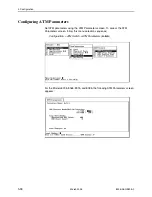
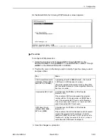
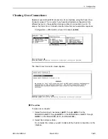
To configure ATM cross connections:
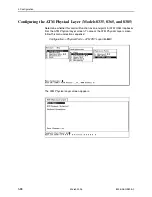
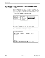
1. Select the interface to be changed (
dsl1:1
through
dsl16:1
on the
Model 8335,
dsl1:1
through
dsl12:1
on the Model 8365, or
dsl1:1
through
dsl24:1
on the Model 8355, 8375, and Model 8385).
2. Select the Index number of the VC (Virtual Channel) you wish to modify, or 0
to add a new VC.
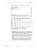
— Total Connections for this Interface shows the number of connections
defined for the interface.
— Available Connections displays the number of connections still available
for the card.
To scroll to the previous or next group of connections, type
u
(for Up) or
d
(for Down) in the Index field.
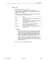
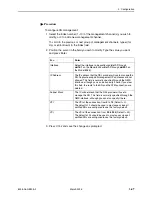
3. Position the cursor in the field you wish to modify. Type the value you want and
press Enter.
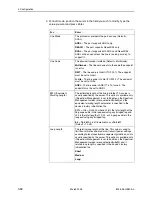
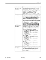
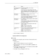
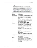
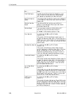
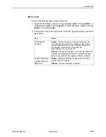
For . . .
Enter . . .
VPI
The VPI (Virtual Path Identifier) of the connection, from
0
to
15
.
VCI
The VCI (Virtual Channel Identifier) of the connection from
32
to
255
.
Profile Name (Models
8335 and 8385)
Tx Profile/Rx Profile
(Models 8355 and
8375)
Dnstream Profile/
Upstream Profile
(Model 8365)
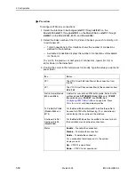
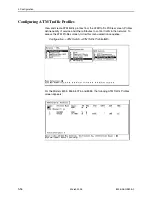
A default or user-defined ATM traffic profile. Default traffic
profiles include
AUTOBAUD
(Model 8335 only),
IP MGT
(Model 8365 only),
PACKET
, and
VOICE.
See
Configuring ATM Traffic Profiles
on page 3-36. Press
Ctrl-v for a list of valid downstream profiles.
For the Model 8355 or Model 8375, define the profile to
be used for ATM traffic both leaving (Tx or downstream)
and entering (Rx or upstream) the interface.
For the Model 8365, define the profile to be used for both
the downstream and upstream connections.
Status
Enable
– To enable the connection.
Disable
– To disable the connection.
Delete
– To delete the connection.
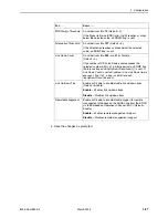
For a connection that already exists, the system
displays one of:
Up
– VPI/VCI is operational.
Down
– VPI/VCI is not operational.

