background image

4. Monitoring the Unit

8700-A2-GB25-10

February 2001

4-7

The following Network Error Statistics are collected for the selected port:

„

ES (Errored Seconds): Seconds during which one or more cyclic redundancy 
check (CRC) error events occurred. A CRC value is calculated for each 
24 frames or 4608 bits of data and is transmitted with the framing information. 
The receiving unit calculates a CRC value for the same 24 frames and 
compares the values. If the values are unequal a CRC error event is logged.

„

SES (Severely Errored Seconds): Seconds during which 320 or more CRC 
error events occurred.

„

FEBE (Far-End Block Errors): CRC errors reported by the remote 
equipment.

„

Complete: Whether the interval register contains data for all 900 seconds of 
the interval.

Fields on this screen include:

Field . . . 

Contains . . . 

Current Interval Timer

The number of seconds which have elapsed in the current 
15-minute interval. Maximum value is 900 seconds 
(15 minutes). This counter is reset every 15 minutes. 
When zero, the port is disabled.

Error Events Counter

A running total of CRC errors. Range 0–65535. This counter 
resets when the near-end data is cleared. When zero, the port is 
disabled.

Current Int

Performance data for the current 15-minute interval. 
When blank, the port is disabled.

Interval 

xx

Historical performance data for up to 96 15-minute intervals 
(24 hours). When blank, the port is disabled.

Worst Interval

The number of the interval with the worst (highest) performance 
data for both the near- and far-end statistics. If two or more 
intervals are equal, the oldest interval is displayed. 
When blank, the port is disabled.

Near and Far Tot

A running total of the near- and far-end performance statistics.

Summary of Contents for Hotwire 8775

Page 1: ...Hotwire TDM SDSL Termination Units Models 8775 and 8785 User s Guide Document No 8700 A2 GB25 10 February 2001 ...

Page 2: ...lp needed For additional information concerning warranty sales service repair installation documentation training distributor locations or Paradyne worldwide office locations use one of the following methods Internet Visit the Paradyne World Wide Web site at www paradyne com Be sure to register your warranty at www paradyne com warranty Telephone Call our automated system to receive current inform...

Page 3: ...guration 1 3 SNMP Management Capabilities 1 4 Management Information Base MIB Support 1 4 SNMP Trap Support 1 4 2 Using the Asynchronous Terminal Interface User Interface Access 2 1 Management Serial Port Settings 2 1 Logging In to the Hotwire DSLAM 2 2 Initiating an ATI Session 2 2 Menu Hierarchy 2 4 Screen Work Areas 2 5 Navigating the Screens 2 6 Keyboard Keys 2 6 Function Keys 2 7 Switching Be...

Page 4: ...g the Unit What to Monitor 4 1 Viewing System and Test Status 4 2 Health and Status Messages 4 3 Self Test Results Messages 4 5 Test Status Messages 4 5 Performance Statistics 4 6 Viewing Network Error Statistics 4 6 Viewing Network Performance Statistics 4 8 Viewing Current Network Performance 4 10 Viewing LED Status 4 11 Front Panel LEDs 4 12 5 Testing Accessing the Test Menu 5 1 Running Network...

Page 5: ...ty Names and Access Types 7 4 Limiting SNMP Access through the IP Addresses of the Managers 7 4 8 IP Addressing Selecting an IP Addressing Scheme 8 1 Configurations Not Running IP Conservative Software 8 1 All Configurations 8 1 IP Addressing Example 8 2 A Configuration Options Overview A 1 Network Interface Options A 2 Synchronous Data Port Options A 4 Copy Ports Options A 7 System Options A 8 Ma...

Page 6: ...00 or 8810 DSLAM C 4 50 Pin Telco Connector Pinouts for Model 8775 in a Hotwire 8820 DSLAM C 5 50 Pin Telco Connector Pinouts for Model 8785 in a Hotwire 8610 DSLAM C 6 50 Pin Telco Connector Pinouts for Model 8785 in a Hotwire 8810 or 8820 DSLAM C 7 100 Pin Plug to Four DB25 Receptacle EIA 530 A Cable C 8 100 Pin Plug to Four MS34 Receptacle V 35 Cable C 12 100 Pin Plug to Four DB37 Receptacle RS...

Page 7: ...des procedures for setting up the user interface and configuring the unit Chapter 4 Monitoring the Unit Describes using the LEDs status and network statistics to monitor the unit Chapter 5 Testing Provides information about available tests and test setup Chapter 6 Messages and Troubleshooting Provides information on SNMP traps device messages and troubleshooting Chapter 7 Security Presents procedu...

Page 8: ...rms acronyms concepts and sections in alphabetical order Section Description Document Number Document Title 7970 A2 GB20 Hotwire TDM SDSL Standalone Termination Units Models 7974 7975 7976 7984 7985 and 7986 User s Guide 8000 A2 GB22 Hotwire Management Communications Controller MCC Card IP Conservative User s Guide 8000 A2 GB29 Hotwire Management Communications Controller MCC Card User s Guide 861...

Page 9: ...tions with maximum loop reaches as shown in Table 1 1 Maximum Loop Reach Hotwire 8775 and 8785 Termination Units are equipped with an automatic configuration capability that reduces the installation process to a simple plug and play mode Simply connecting the units to the line automatically configures the customer for the maximum data rate supported by the local loop Units can also be configured a...

Page 10: ...minal interface for configuring and managing the unit locally or remotely by Telnet session Local Management Provides local management using the DSLAM s management card with a Terminal or PC via the Management Serial port of the DSLAM Network Management System NMS via the Management MCC port of the 8600 Series DSLAM or 10BaseT port of the 8800 Series DSLAM Remote Management Provides remote managem...

Page 11: ... router and frame relay encapsulated or unframed data Figure 1 1 Sample CO to CP Configuration Figure 1 2 Sample Campus Configuration shows termination units used to distribute T1 lines over a campus Figure 1 2 Sample Campus Configuration Frame Relay Switch Router E1 Host Frame Relay Encapsulated Data 99 16520 Router Frame Relay Encapsulated Data V 35 V 35 V 35 Router 2 048 Mb over DSL V 35 V 35 V...

Page 12: ...iguration status statistics and tests SNMP Trap Support The unit supports traps as defined in RFC 1215 They may include variable bindings specified in the following MIBs MIB II RFC 1573 Defines the general objects for use with a network management protocol in TCP IP internets and provides general information about the termination unit MIB II is backward compatible with MIB I Enterprise MIB Support...

Page 13: ...C NOTE Only one ATI session can be active at a time and another user s session cannot be forced to end To automatically log out a user due to inactivity enable the Inactivity Timeout option To enable the Inactivity Timeout option refer to Table A 5 Telnet Session Options in Appendix A Configuration Options Security can limit ATI access several ways To set up security or a login ID refer to Chapter...

Page 14: ...I Session The Main Menu screen is displayed unless a login ID and password is required or the ATI is already in use If the ATI is already in use the message connection refused is sent to a terminal attempting Telnet access If security is enabled and Telnet is used to access the terminal unit directly you did not log in through the MCC the system prompts you for a login ID and password If you enter...

Page 15: ... for each interface and each user Data selection criteria What you entered in previous screens main Access Level Administrator Hotwire Slot 4 Model 87x5 MAIN MENU Status Test Configuration Control Ctrl a to access these functions Exit Screen Area Function Keys and Message Area Select To Status View system status diagnostic test results statistics LED and device identity information Test Select sta...

Page 16: ...istics Network Performance Statistics Configuration Control Default Factory Configuration Configuration Loader Current Configuration Network SYNC Ports Copy Ports System Options Management and Communication Telnet Session General SNMP Management SNMP NMS Security SNMP Traps Change Identity Administer Logins Download Code Apply Download Reset AutoRate Network Tests SYNC Data Port Tests Device Tests...

Page 17: ...rent Configuration Network Function keys and message area This is the area below the dotted line that lists function keys specific to the screen field value choices and system messages main config network Hotwire Slot 4 Model 87x5 Port 3 NETWORK INTERFACE OPTIONS Margin Threshold 3db Excessive Error Rate Threshold 1E 5 AutoRate Disable DSL Line rate 2064 Circuit Identifier Clear Ctrl a to access t...

Page 18: ...on keys area below the dotted line at the bottom of the screen Esc Return to the previous screen Tab Move cursor to the next field on the screen Backspace Move cursor to the previous field on the screen Enter Accept entry or display valid options on the last row of the screen when pressed before entering data or after entering invalid data Ctrl k Tab backwards move cursor one field to the left Spa...

Page 19: ...ssing the spacebar to scroll through other valid values Press Enter to select the value Function Keys All function keys located below the dotted line operate the same way upper or lowercase throughout the screens For the screen function Select And press Enter to ClrFar F or f Clear far end network statistics and refresh the screen ClrNear N or n Clear near end network statistics and refresh the sc...

Page 20: ...ed line 2 Select either the function s designated underlined character or press the Tab key until you reach the desired function key Example To save the current options type s or S Save 3 Press Enter The function is performed 4 To return to the screen area above the dotted line press Ctrl a again main config network Hotwire Slot 4 Model 87x5 Port 3 NETWORK INTERFACE OPTIONS Margin Threshold 3db Ex...

Page 21: ...ess Enter If you have accessed the unit through the management card the Hotwire Chassis Card Selection menu appears Exiting From the DSLAM Session You can manually log out of the system or after five minutes of inactivity the system will automatically log you out if the inactivity time out option is enabled Procedure To manually exit from the Hotwire DSLAM system 1 Return to the Hotwire Chassis Ma...

Page 22: ...2 Using the Asynchronous Terminal Interface 2 10 February 2001 8700 A2 GB25 10 ...

Page 23: ...unit These procedures include Entering Identity Information on page 3 2 Configuring the Unit on page 3 3 Current and Default Factory Configurations on page 3 4 Configuration Loader on page 3 5 Saving Configuration Options on page 3 7 Downloading Firmware on page 3 8 AutoRate Feature on page 3 10 Disabling AutoRate on page 3 10 Resetting AutoRate on page 3 11 Restoring Access to the User Interface ...

Page 24: ...stem Name The general SNMP system name System Location The physical location of the SNMP managed device System Contact Identification information such as contact name phone number or mailing address Valid entry values are any printable ASCII character ASCII printable characters include Numeric 0 9 Uppercase or lowercase A Z Space All ASCII symbols except the caret Select Clear to reset a field to ...

Page 25: ... 5 Select Save and press Enter Configuring the Unit Configuration option settings determine how the termination unit operates Use the Configuration menus to select display or change configuration option settings The unit is shipped with factory settings that match the options and settings in the Default Factory Configuration area To display configuration options follow this menu selection sequence...

Page 26: ...as been misconfigured In the menu selection sequences contained in this manual Current Configuration is assumed and shown If you select Then Current Configuration The selected configuration option set is loaded and the Configuration Edit Display menu appears This is the unit s currently active configuration Configuration Loader The Configuration Loader screen is displayed allowing you to upload or...

Page 27: ...rts Copy Ports Options Table A 3 DSL network and DTE ports by copying options from port to port System Options System Options Table A 4 General system options of the unit Management and Communication Telnet Session Options Table A 5 General SNMP Management Options Table A 6 SNMP NMS Security Options Table A 7 SNMP Trap Options Table A 8 Management support of the unit through SNMP and Telnet main c...

Page 28: ...e cursor in the TFTP Server IP Address field Enter the TFTP server IP address The first three digits of the IP address cannot be 000 or greater than 223 3 Position the cursor in the TFTP Transfer Direction field Use the spacebar to select Download from Server or Upload to Server 4 Position the cursor in the Destination field Use the spacebar to select a network destination for the TFTP server Sele...

Page 29: ...o disconnect Do not answer Yes unless you are prepared to disconnect If the DSL Mode configuration option is changed a message displays on the Save Configuration screen warning that an answer of Yes will cause the system to reset Do not answer Yes unless you are prepared to reset the unit NOTE When Exit is selected before Save or Save has been selected from any Configuration Edit menu a Save Confi...

Page 30: ...digits of the IP address cannot be 000 or greater than 223 3 Position the cursor in the Destination field Use the spacebar to select a network destination for the TFTP server 4 Position the cursor in the Immediately Apply Download field If you would like the download to be effective immediately select Yes 5 Position the cursor at the Start Transfer field Use the spacebar to select Yes Press Enter ...

Page 31: ...e card and activate the code Selecting Yes causes the termination unit to reset NOTE The unit has two flash memory banks to hold executable firmware You can switch between these two firmware versions by applying the firmware listed on the Apply Download screen main control apply_download Hotwire Model 87x5 APPLY DOWNLOAD Switch To Code Revision A01 00 02 No WARNING An answer of yes will cause the ...

Page 32: ...creen follow this menu selection sequence Main Menu Configuration Current Configuration Network The AutoRate option defaults to Enable Procedure To disable AutoRate 1 Position the cursor in the AutoRate field and press the spacebar The AutoRate field toggles to Disable and the DSL Line Rate field appears 2 Enter a DSL Line Rate and press Enter Your payload rate is set to a default value determined...

Page 33: ...when AutoRate is enabled If the link fails the next lower rate is tried until the link is established To access the Reset AutoRate screen follow this menu selection sequence Main Menu Control Reset AutoRate Table 3 1 Selectable Payload Rates When AutoRate Is Disabled DSL Line Rate kbps Selectable Payload Rates kbps default in boldface type 144 128 64 272 256 192 400 384 320 528 512 448 784 768 704...

Page 34: ...tering Y restores the Default Factory Configuration 5 Enter Y at the prompt to confirm NOTE When you enter Y all data connectivity is interrupted You can also restore access to the user interface by reloading the Default Factory Configuration options using the unit s menus Procedure To restore access to the ATI using the unit s menus Main Menu Configuration Default Factory Configuration Resetting ...

Page 35: ...you can monitor unit operations Viewing System and Test Status on page 4 2 Health and Status Messages on page 4 3 Self Test Results Messages on page 4 5 Test Status Messages on page 4 5 Performance Statistics on page 4 6 Viewing Network Error Statistics on page 4 6 Viewing Network Performance Statistics on page 4 8 Viewing Current Network Performance on page 4 10 Viewing LED Status on page 4 11 Fr...

Page 36: ...esults Messages Test Status Currently active tests Refer to Table 4 3 Test Status Messages main status system Hotwire Slot 4 Model 87x5 SYSTEM AND TEST STATUS Page 1 of 1 HEALTH AND STATUS SELF TEST RESULTS TEST STATUS LOS at Net Pt n CPU Failed No Test Active OOF at Net Pt n Device Failed LLB Test Active Pt n EER at Net Pt n Net DSL Failed Pt n RLB Test Active Pt n SYNC Pt Down Pt n SYNC Pt Faile...

Page 37: ...hreshold value currently configured 1 Ignore condition if a Send and Monitor 511 test is active 2 Check the Network Performance Statistics screen for possible line impairments 3 Set the unit to run at a lower DSL line rate 4 Raise the EER Threshold 5 Contact network provider Fallback Rate Pt n The LTU set to AutoRate enable had a LOS when the line was restored and resynched at a lower rate 1 Ignor...

Page 38: ...unit to Internal External or Loop timing 2 If the unit is configured as an LTU verify that Transmit Clock Source is set to External and that the synchronous port is providing valid clocking 3 Check the Network Performance Statistics screen for possible line impairments 4 Set the unit to run at a lower DSL line rate 5 Contact network provider SYNC Pt Down Pt n The interchange circuits for Port n ar...

Page 39: ... failure code and contact your service representative Memory Failed The unit failed memory verification 1 Reset the unit and try again 2 Call your service representative for assistance Net DSL Failed Pt n The unit failed to loop data on the network DSL circuit of Port n SYNC Pt Failed Pt n The unit failed to internally loop data on the synchronous Port n Passed No errors were detected No action is...

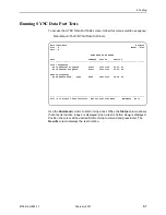
Page 40: ...the network DSL interface for each port To view Network Error Statistics for a port follow this menu selection sequence Main Menu Status Performance Statistics Network Error Statistics main status performance net_error Hotwire Slot 4 Model 87x5 Port 3 NETWORK ERROR STATISTICS Current Interval Timer 2 Error Events Counter 34 ES SES FEBE Complete Near Far Near Far Near Far Near Far Current Int 000 0...

Page 41: ...he interval Fields on this screen include Field Contains Current Interval Timer The number of seconds which have elapsed in the current 15 minute interval Maximum value is 900 seconds 15 minutes This counter is reset every 15 minutes When zero the port is disabled Error Events Counter A running total of CRC errors Range 0 65535 This counter resets when the near end data is cleared When zero the po...

Page 42: ...nger reaches XmtPw The transmit power level The maximum level is 15 dBm RxGn The receiver gain level This is the amount the unit must boost the receive signal It is not a receive level measurement Complete Whether the interval register contains data for all 900 seconds of the interval main status performance net_perf Hotwire Slot 4 Model 87x5 Port 3 NETWORK PERFORMANCE STATISTICS Current Interval ...

Page 43: ... number of seconds which have elapsed in the current 15 minute interval Maximum value is 900 seconds 15 minutes This counter resets every 15 minutes DSL Line Rate The rate of the DSL line Current Int Performance data for the current 15 minute interval Interval xx Historical performance data for up to 96 15 minute intervals 24 hours ...

Page 44: ... Error Rate BER of 10 7 or better XmtPw The transmit power level RxGn The receiver gain level The following Network Error Statistics are collected for the selected port ES Errored Seconds Seconds during which one or more ESF error events occurred SES Severely Errored Seconds Seconds during which more than 320 cyclic redundancy check CRC error events or at least one Out of Frame OOF event occurred ...

Page 45: ... Status Display LEDs The LED status display screen is updated every 5 seconds For information about the meaning of the LEDs see Front Panel LEDs on page 4 12 Field Contains Current Interval Timer The number of seconds which have elapsed in the current 15 minute interval Maximum value is 900 seconds 15 minutes This counter is reset every 15 minutes When zero the port is disabled Payload Rate The ra...

Page 46: ... and a download is required Normal operation Alrm Amber On Off Device failure or the Power On Self Test POST has failed No alarms Test Amber On Slow cycling Off Loopback test or 511 test pattern is in progress POST is in progress No tests are active SYNC PORT 1 2 3 4 Green On Off The port is operational No signal is detected on the port or DTR or RTS is off DSL PORT LINK UP 1 2 3 4 Green On Slow c...

Page 47: ... stop tests on the network interface SYNC Data Port Tests Start and stop tests on the DTE interface Device Tests Start and stop a lamp test Abort All Tests To abort all currently active tests Network initiated tests will not be affected An aborted test may continue to run for a few seconds as the abort command is sent to the remote end and processed main test Hotwire Slot 4 Model 87x5 TEST Network...

Page 48: ...ion Selecting a Stop command on the Network Tests screen or Abort All Tests from the Test menu will not disrupt a network initiated loopback When the Send and Monitor 511 test is active ResetMon is available to reset the error counter to zero main test network Hotwire Slot 4 Model 87x5 Port 4 NETWORK TESTS Test Command Status Results Local Loopbacks Line Loopback Start Inactive 00 00 00 Repeater L...

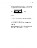
Page 49: ...mmand next to Line Loopback on the Network Tests screen 2 Press Enter The Start command is changed to Stop 3 To manually stop the test verify that the cursor is positioned at the Stop command 4 Press Enter The Line Loopback cannot be started when a Repeater Loopback Data Channel Loopback DCLB Remote DCLB or network initiated Line Loopback is in progress 98 15931 NTU LTU Network Interface All 1s Po...

Page 50: ... Network Tests screen 2 Press Enter The Start command is changed to Stop 3 To manually stop the test verify that the cursor is positioned at the Stop command 4 Press Enter The Repeater Loopback cannot be started when a Line Loopback DCLB Remote DCLB or Data Terminal Loopback DTLB is active NOTE If a disconnected DSL loop is connected while a Repeater Loopback is active the connected units will not...

Page 51: ...1 Position the cursor at the Up or Down selection next to Send Line Loopback on the Network Tests screen 2 Press the spacebar to select either Up or Down 3 Position the cursor at the Send command next to Up or Down selection 4 Press Enter The loopback stops automatically after 10 seconds You cannot stop the test manually The Remote Send Line Loopback cannot be started when any other loopback or a ...

Page 52: ...n the cursor at the Start command next to Send and Monitor 511 on the Network Tests screen 2 Press Enter The Start command is changed to Stop 3 To manually stop the test verify that the cursor is positioned at the Stop command 4 Press Enter When a Send and Monitor 511 test is active a count of bit errors is displayed next to the test duration and the ResetMon virtual function key is available for ...

Page 53: ...layed when a test is Active Stop is displayed Position the cursor at the desired Start or Stop command and press Enter The Results column displays the test duration main test data Hotwire Slot 4 Model 87x5 Port 4 SYNC DATA PORT TESTS Test Command Status Results Local Loopbacks Data Terminal Loopback Start Inactive 00 00 00 Data Channel Loopback Start Inactive 00 00 00 Remote Loopbacks Send Remote ...

Page 54: ...Position the cursor at the Start command next to Data Terminal Loopback on the SYNC Data Port Tests screen 2 Press Enter The Start command is changed to Stop 3 To manually stop the test verify that the cursor is positioned at the Stop command 4 Press Enter The Data Terminal Loopback cannot be started when a Repeater Loopback DCLB or Remote DCLB is already active on the data port 98 15933 NTU LTU N...

Page 55: ...t command next to Data Channel Loopback on the SYNC Data Port Tests screen 2 Press Enter The Start command is changed to Stop 3 To manually stop the test verify that the cursor is positioned at the Stop command 4 Press Enter The Data Channel Loopback cannot be started when any of the following tests is active Send and Monitor 511 Line Loopback or Repeater Loopback on the network interface or a Dat...

Page 56: ...lection next to Send Remote DCLB on the SYNC Data Port Tests screen 2 Press the spacebar to select the desired code Up or Down 3 Position the cursor at the Start command next to Send Remote DCLB on the SYNC Data Port Tests screen 4 Press Enter The Status field is changed to Sending The Up or Down sequence transmission stops automatically after 10 seconds You cannot stop the sequence manually The S...

Page 57: ...the LEDs 1 Position the cursor at the Start command next to Lamp Test on the Device Tests screen 2 Press Enter The Start command is changed to Stop During the Lamp Test all LEDs blink simultaneously every second When you stop the Lamp Test the LEDs are restored to their normal condition 3 To stop the Lamp Test position the cursor at the Stop command 4 Press Enter main test card Hotwire Slot 4 Mode...

Page 58: ...unit terminates the test The default is 10 minutes Refer to Table A 4 System Options in Appendix A Configuration Options Command column Under the Command column on any test screen position the cursor at Stop next to the active test and press Enter to stop a specific test Abort All Tests menu selection Select Abort All Tests from the Test menu to stop all tests running on all interfaces Command Com...

Page 59: ...oubleshooting Overview There are many messages available to assess the status of the device and contribute to problem resolutions Refer to the following sections Configuring SNMP Traps on page 6 2 Device Messages on page 6 3 Troubleshooting on page 6 5 ...

Page 60: ...ct the type of SNMP traps to be sent from the unit To configure SNMP Traps follow this menu selection sequence Main Menu Configuration Current Configuration Management and Communication SNMP Traps Refer to Table A 8 SNMP Trap Options in Appendix A Configuration Options for information about these options main config management trap Hotwire Slot 4 Model 87x5 SNMP TRAPS OPTIONS SNMP Traps Enable Num...

Page 61: ...ly completed No action is needed Invalid Character x A nonprintable ASCII character x has been entered Reenter information using valid characters Invalid Data Terminal Initiated Loopback Active Network initiated loopback was in progress when another selection was made No action is needed Invalid Password Login is required and an incorrect password was entered access is denied Try again Contact you...

Page 62: ...ded Enter a security record Password Matching Error Re enter Password Password entered in the Re enter Password field of the Administer Logins screen does not match what was entered in the Password field Try again Contact your system administrator to verify your password Please Wait Command takes longer than 5 seconds Wait until message clears Test Active A test is running and no higher priority h...

Page 63: ...ternal hardware failure Reset the unit Contact your service representative No power or the LEDs are not lit The unit is not properly seated in the DSLAM Verify that the unit is properly inserted There is no power to the DSLAM Verify that the chassis has power An LED is not lit LED is out Run the Lamp Test If the LED in question does not flash with the other LEDs then contact your service represent...

Page 64: ...6 Messages and Troubleshooting 6 6 February 2001 8700 A2 GB25 10 ...

Page 65: ... to Login IDs and Telnet sessions When access is through Telnet and a login is required for Telnet the effective access level is the more restrictive of the Telnet session access level or the login access level see Table A 5 Telnet Session Options in Appendix A Configuration Options When an access level of Operator is applied to Telnet sessions a Login ID with Administrator authority is effectivel...

Page 66: ...ntrol Administer Logins 2 Select New and press Enter The Login Entry screen is displayed main control admin_logins Hotwire Slot 4 Model 87x5 ADMINISTER LOGINS Page 1 of 1 Login ID newuser Access Level Administrator Are You Sure Yes ESC for previous menu MainMenu Exit Save PgUp PgDn New Delete main control admin_logins Hotwire Slot 4 Model 87x5 LOGIN ENTRY Login ID newuser Password e34t136 Re enter...

Page 67: ...rd follow this menu selection sequence Main Menu Control Administer Logins 2 Select PgUp or PgDn and press Enter to page through login pages records until you find the one to be deleted 3 Once the correct record is displayed select Delete and press Enter 4 To complete the delete action select Save and press Enter When the deletion is complete Command Complete appears at the bottom of the screen Th...

Page 68: ... Management Options in Appendix A Configuration Options to Enable SNMP Management Assign the SNMP community names of the SNMP Managers that are allowed to access the units Management Information Base MIB Specify Read or Read Write access for each SNMP community name Limiting SNMP Access through the IP Addresses of the Managers The unit provides an additional level of security through validation of...

Page 69: ...address is assigned you can use the ATI to assign Peer IP addresses to the four DSL ports These addresses are used as the IP addresses of the remote units See Table A 1 Network Interface Options in Appendix A Configuration Options An IP address for each NMS to act as a trap manager See Table A 8 SNMP Trap Options in Appendix A Configuration Options All Configurations The NTU obtains its IP address...

Page 70: ...Peer IP Address Assignments for an example of an IP addressing scheme In the example the Peer IP Address Refers to the IP address of the unit configured as an NTU Is assigned by the LTU Figure 8 1 Peer IP Address Assignments 99 16040 02 DSLAM DSLAM 79xx 79xx 79xx MCC Base Address 126 35 50 1 MCC Base Subnet Mask 255 255 255 0 Port 1 Peer IP Address 126 35 1 5 MCC LTU 87xx Port 2 Peer IP Address 12...

Page 71: ...t To Access the To Configure the Network Network Interface Options Table A 1 DSL network interface Ports 1 4 SYNC Ports Synchronous Data Port Options Table A 2 Synchronous DTE interface Ports 1 4 Copy Ports Copy Ports Options Table A 3 DSL network and synchronous DTE interface ports by copying options from port to port System System Options Table A 4 General system options of the unit Management a...

Page 72: ...ld to this value Excessive Error Rate Threshold Possible Settings 1E 4 1E 5 1E 6 1E 7 1E 8 1E 9 Default Setting 1E 6 Determines the error rate at which an excessive error rate EER condition is recognized The rate is the ratio of the number of CRC errors to the number of bits received in a certain period 1E 4 to 1E 9 Sets the excessive error rate threshold to this value AutoRate Possible Settings E...

Page 73: ...ayload rates are 1600 1664 1728 1792 1856 1920 1984 and 2048 kbps Peer IP Address Possible Settings 001 000 000 000 223 255 255 255 Clear Default Setting 000 000 000 000 Specifies the peer IP address providing the remote management link on the DSL loop Peer IP Address is only available when the unit is configured as an LTU and the unit is not running in IP Conservative mode 001 000 000 000 223 255...

Page 74: ... 1344 1408 1472 1536 1600 1664 1728 1792 1856 1920 1984 2048 Default Setting 2048 Specifies the payload rate of the port See DSL Line Rate in Table A 1 Network Interface Options for payload rates allowed at different DSL line rates Payload Rate is available only if the unit is configured as an LTU and AutoRate is disabled NOTE Payload rates of 1088 kbps and higher are available only with 2 Mbps te...

Page 75: ...dy interchange circuit CD ITU T 108 1 2 When DTR is interrupted all ones are sent to the network RTS Monitors the Request to Send interchange circuit CA ITU T 105 When RTS is interrupted all ones are sent to the network Action on Network LOS Alarm Possible Settings Halt None Default Setting Halt Specifies the action taken on the synchronous data port when an LOS Loss Of Signal alarm is received on...

Page 76: ...141 DCLB Gives control of the remote DCLBs for the far end port connected to this port to the DTE attached to this port This loopback is controlled by the Remote Loopback interchange circuit RL ITU T 140 The far end equipment must support in band V 54 loopbacks Both Gives control of local DTLBs and remote DCLBs to the DTE connected to this port Elastic Store Possible Settings Disable Enable Defaul...

Page 77: ...e A 3 Copy Ports Options From Port Possible Settings 1 2 3 4 Default Setting 1 Controls the source of the configuration options 1 4 The configuration of the selected port is copied To Port Possible Settings 1 2 3 4 All Default Setting 2 Controls the target of the configuration options 1 4 The configuration of the selected port is replaced If Perform Copy Then Increment is selected the port number ...

Page 78: ...tion will reset the unit Test Timeout Possible Settings Enable Disable Default Setting Enable Allows user initiated tests to end automatically The feature should be enabled when the unit is remotely managed so that control can be regained after a test is accidentally executed Enable User initiated loopback and pattern tests end when test duration is reached Disable Tests must be terminated manuall...

Page 79: ...ble No Telnet sessions allowed Telnet Login Required Possible Settings Enable Disable Default Setting Disable Used to secure access to the ATI through a Telnet session Login IDs are created with a password and access level Refer to Creating a Login in Chapter 7 Security Enable Security is enabled When access is attempted via Telnet the user is prompted for a Login ID and password Disable No Login ...

Page 80: ...ically after the Disconnect Time Disable A Telnet session will not be closed due to inactivity Disconnect Time Minutes Possible Settings 1 60 Default Setting 5 Number of minutes of inactivity before a Telnet session terminates automatically Timeout is based on no keyboard activity Disconnect Time minutes appears when Inactivity Timeout is enabled It does not appear when the unit is connected to a ...

Page 81: ... attempts to access an object in the MIB ASCII text field Enter or edit a community name Clear Clears the community name field Name 1 Access Possible Settings Read Read Write Default Setting Read Determines the access level for Community Name 1 Read Allows read only access get for Community Name 1 Read Write Allows read write access get for Community Name 1 Community Name 2 Possible Settings ASCII...

Page 82: ...Specifies the number of SNMP management systems that can send SNMP messages 1 10 Number of trap managers An NMS IP address is required for each manager NMS n IP Address Possible Settings 001 000 000 000 223 255 255 255 Clear Default Setting 000 000 000 000 Specifies the Internet Protocol address used to identify each SNMP manager 001 000 000 000 223 255 255 255 Enter an address for each SNMP manag...

Page 83: ...required for each manager NMS n IP Address Possible Settings 001 000 000 000 223 255 255 255 Clear Default Setting 000 000 000 000 Specifies the Internet Protocol address used to identify each SNMP trap manager This field is not available when the unit is running in IP Conservative mode 001 000 000 000 223 255 255 255 Enter an address for each SNMP trap manager The range for the first byte is 001 ...

Page 84: ...ault Setting Both Determines if SNMP traps are generated for link up and link down for one of the communication interfaces Disable No linkUp or linkDown SNMP traps are generated Up A linkUp trap is generated when the unit recognizes that one of the communication interfaces is operational Down A linkDown trap is generated when the unit recognizes a failure in one of the communication interfaces Bot...

Page 85: ...cationFailure linkUp and linkDown warmStart authenticationFailure SNMP Trap Description Possible Cause warmStart The unit has reinitialized itself The trap is sent after the unit resets and stabilizes There are no variable bindings Reset command Power disruption SNMP Trap Description Possible Cause authenticationFailure Failed attempts to access the unit There are no variable bindings Three unsucc...

Page 86: ... all indexes are supported for each model The ifIndex included with the trap consists of the slot number times 1000 plus 2DSL Interface Port 1 3DSL Interface Port 2 4DSL Interface Port 3 5DSL Interface Port 4 10Synchronous Data Port Port 1 11Synchronous Data Port Port 2 12Synchronous Data Port Port 3 13Synchronous Data Port Port 4 ifAdminStatus RFC 1573 This object specifies the operational state ...

Page 87: ...are has detected an internal device failure enterpriseTestStart 5 A test is running At least one test has been started on an interface enterpriseConfigChange 6 The configuration changed via the user interface The trap is sent after 60 seconds have elapsed without another change This suppresses the sending of numerous traps when multiple changes are made in a short period of time as is typically th...

Page 88: ...est testSendLLBUp Initiates an LLB Up message to the remote unit testSendLLBDown Initiates an LLB Down message to the remote unit enterpriseTest Start Any one of the following tests is active on the interface Line Loopback Repeater Loopback Remote Line Loopback Send and Monitor 511 enterpriseTest Stop No tests currently running on the interface Synchronous Data Ports ifIndex RFC 1573 ifAdminStatus...

Page 89: ...0 Pin Telco Connector Pinouts for Model 8785 in a Hotwire 8610 DSLAM on page C 6 50 Pin Telco Connector Pinouts for Model 8785 in a Hotwire 8810 or 8820 DSLAM on page C 7 100 Pin Plug to Four DB25 Receptacle EIA 530 A Cable on page C 8 100 Pin Plug to Four MS34 Receptacle V 35 Cable on page C 12 100 Pin Plug to Four DB37 Receptacle RS 449 Cable on page C 16 100 Pin Plug to Four DB15 Receptacle X 2...

Page 90: ...aces NOTE When the 8600 chassis is the base chassis the Management Communications Controller MCC is installed in Slot 1 the Tips and Rings for Slot 1 are not connected internally and are not active Table C 1 8600 LINE Connector Pinouts LINE Connector Card Port Connector Pins Tip Ring Card 1 Port 1 1 26 Card 1 Port 2 2 27 Card 1 Port 3 3 28 Card 1 Port 4 4 29 Card 2 Port 1 5 30 Card 2 Port 2 6 31 C...

Page 91: ...rface from each DSL port to the MDF The following table lists the pin assignments for each of these interfaces NOTE When the 8610 chassis is the base chassis the Management Control Processor MCP is installed in Slot 1 the Tips and Rings for Slot 1 are not connected internally and are not active Table C 2 8610 Connector 1 3 Pinouts Connector 1 3 Port Connector Pins Tip Ring Port 1 1 26 Port 2 2 27 ...

Page 92: ...ort 1 Card 8 Port 1 Card 14 Port 1 5 30 Card 2 Port 2 Card 8 Port 2 Card 14 Port 2 6 31 Card 2 Port 3 Card 8 Port 3 Card 14 Port 3 7 32 Card 2 Port 4 Card 8 Port 4 Card 14 Port 4 8 33 Card 3 Port 1 Card 9 Port 1 Card 15 Port 1 9 34 Card 3 Port 2 Card 9 Port 2 Card 15 Port 2 10 35 Card 3 Port 3 Card 9 Port 3 Card 15 Port 3 11 36 Card 3 Port 4 Card 9 Port 4 Card 15 Port 4 12 37 Card 4 Port 1 Card 10...

Page 93: ...Pin Telco receptacles on the rear of the chassis labeled 1 18 provide the 2 wire loop interface from each DSL port to the MDF The following table lists the pin assignments for each of these interfaces Table C 4 8820 Connector 1 18 Pinouts Connector 1 18 Port Connector Pins Tip Ring Port 1 1 26 Port 2 2 27 Port 3 3 28 Port 4 4 29 26 97 15526 50 1 25 ...

Page 94: ...llowing table lists the pin assignments for each of these interfaces NOTE When the 8610 chassis is the base chassis the Management Control Processor MCP is installed in Slot 1 the Tips and Rings for Slot 1 are not connected internally and are not active Table C 5 8610 Connector 1 3 Pinouts Connector 1 3 Port Direction Connector Pins Tip Ring Port 1 RX 4 29 Port 1 TX 5 30 Port 2 RX 6 31 Port 2 TX 7...

Page 95: ...hassis labeled 1 18 provide the 2 wire loop interface from each DSL port to the MDF The following table lists the pin assignments for each of these interfaces Table C 6 8810 and 8820 Connector 1 18 Pinouts Connector 1 18 Port Direction Connector Pins Tip Ring Port 1 RX 4 29 Port 1 TX 5 30 Port 2 RX 6 31 Port 2 TX 7 32 Port 3 RX 8 33 Port 3 TX 9 34 Port 4 RX 10 35 Port 4 TX 11 36 26 97 15526 50 1 2...

Page 96: ...t 1 3 RD A 61 PORT1_RD_L Port 1 16 RD B 11 PORT1_RXC_H Port 1 17 RXC A 60 PORT1_RXC_L Port 1 9 RXC B 9 PORT1_TT_H Port 1 24 XTXC A 58 PORT1_TT_L Port 1 11 XTXC B 52 PORT1_RTS_H Port 1 4 RTS A 2 PORT1_RTS_L Port 1 19 RTS B 55 PORT1_CTS_H Port 1 5 CTS A 5 PORT1_CTS_L Port 1 13 CTS B 4 PORT1_LSD_H Port 1 8 CD A 53 PORT1_LSD_L Port 1 10 CD B 54 PORT1_DSR Port 1 6 DSR 3 PORT1_DTR Port 1 20 DTR 6 PORT1_...

Page 97: ... Port 2 8 CD A 65 PORT2_LSD_L Port 2 10 CD B 66 PORT2_DSR Port 2 6 DSR 15 PORT2_DTR Port 2 20 DTR 18 PORT2_TM Port 2 25 TM N C N C 63 PORT2_LL Port 2 18 LL 68 GND Port 2 7 GND 19 PORT2_RL Port 2 21 RL 74 GND Port 2 23 GND Port 2 Port 2 22 23 RI GND 32 PORT3_TD_H Port 3 2 TD A 81 PORT3_TD_L Port 3 14 TD B 34 PORT3_TXC_H Port 3 15 TXC A 83 PORT3_TXC_L Port 3 12 TXC B 36 PORT3_RD_H Port 3 3 RD A 85 P...

Page 98: ...ORT3_RL Port 3 21 RL 86 GND Port 3 23 GND Port 3 Port 3 22 23 RI GND 44 PORT4_TD_H Port 4 2 TD A 93 PORT4_TD_L Port 4 14 TD B 46 PORT4_TXC_H Port 4 15 TXC A 95 PORT4_TXC_L Port 4 12 TXC B 48 PORT4_RD_H Port 4 3 RD A 97 PORT4_RD_L Port 4 16 RD B 47 PORT4_RXC_H Port 4 17 RXC A 96 PORT4_RXC_L Port 4 9 RXC B 45 PORT4_TT_H Port 4 24 XTXC A 94 PORT4_TT_L Port 4 11 XTXC B 88 PORT4_RTS_H Port 4 4 RTS A 38...

Page 99: ...42 PORT4_TM Port 4 25 TM N C N C 87 PORT4_LL Port 4 18 LL 92 GND Port 4 7 GND 43 PORT4_RL Port 4 21 RL 98 GND Port 4 23 GND Port 4 Port 4 22 23 RI GND 49 37 CABLE_ID GND 100 Pin plug Shield Port 1 Port 2 Port 3 Port 4 1 1 1 1 SHIELD SHIELD SHIELD SHIELD Table C 7 EIA 530 A Cable Pinouts 4 of 4 100 Pin Plug Net Name DB25 Socket Pin Number Net Name ...

Page 100: ..._L Port 1 AA TXC B 12 PORT1_RD_H Port 1 R RD A 61 PORT1_RD_L Port 1 T RD B 11 PORT1_RXC_H Port 1 V RXC A 60 PORT1_RXC_L Port 1 X RXC B 9 PORT1_TT_H Port 1 U XTXC A 58 PORT1_TT_L Port 1 W XTXC B 52 PORT1_RTS_H Port 1 C RTS N C N C 55 PORT1_CTS_H Port 1 D CTS N C N C 4 PORT1_LSD_H Port 1 F RLSD N C N C 3 PORT1_DTR Port 1 H DTR 54 PORT1_DSR Port 1 E DSR 6 PORT1_TM Port 1 NN TM N C N C 51 PORT1_LL Por...

Page 101: ... F RLSD N C N C 15 PORT2_DTR Port 2 H DTR 66 PORT2_DSR Port 2 E DSR 18 PORT2_TM Port 2 NN TM N C N C 63 PORT2_LL Port 2 L LL 68 GND Port 2 B GND 19 PORT2_RL Port 2 N RL 74 GND Port 2 B GND Port 2 Port 2 J B CI GND 32 PORT3_TD_H Port 3 P TD A 81 PORT3_TD_L Port 3 S TD B 34 PORT3_TXC_H Port 3 Y TXC A 83 PORT3_TXC_L Port 3 AA TXC B 36 PORT3_RD_H Port 3 R RD A 85 PORT3_RD_L Port 3 T RD B 35 PORT3_RXC_...

Page 102: ...RL Port 3 N RL 86 GND Port 3 B GND Port 3 Port 3 J B CI GND 44 PORT4_TD_H Port 4 P TD A 93 PORT4_TD_L Port 4 S TD B 46 PORT4_TXC_H Port 4 Y TXC A 95 PORT4_TXC_L Port 4 AA TXC B 48 PORT4_RD_H Port 4 R RD A 97 PORT4_RD_L Port 4 T RD B 47 PORT4_RXC_H Port 4 V RXC A 96 PORT4_RXC_L Port 4 X RXC B 45 PORT4_TT_H Port 4 U XTXC A 94 PORT4_TT_L Port 4 W XTXC B 88 PORT4_RTS_H Port 4 C RTS N C N C 91 PORT4_CT...

Page 103: ...SR 42 PORT4_TM Port 4 NN TM N C N C 87 PORT4_LL Port 4 L LL 92 GND Port 4 B GND 43 PORT4_RL Port 4 N RL 98 GND Port 4 B GND Port 4 Port 4 J B CI GND 100 Pin Plug Shield Port 1 Port 2 Port 3 Port 4 A A A A SHIELD SHIELD SHIELD SHIELD Table C 8 V 35 Cable Pinouts 4 of 4 100 Pin Plug Net Name MS34 Socket Pin Number Net Name ...

Page 104: ...RD_H Port 1 6 RD A 61 PORT1_RD_L Port 1 24 RD B 11 PORT1_RXC_H Port 1 8 RT A 60 PORT1_RXC_L Port 1 26 RT B 9 PORT1_TT_H Port 1 17 TT A 58 PORT1_TT_L Port 1 35 TT B 52 PORT1_RTS_H Port 1 7 RS A 2 PORT1_RTS_L Port 1 25 RS B 55 PORT1_CTS_H Port 1 9 CS A 5 PORT1_CTS_L Port 1 27 CS B 4 PORT1_LSD_H Port 1 13 RR A 53 PORT1_LSD_L Port 1 31 RR B 54 PORT1_DSR Port 1 11 DM A 3 PORT1_DTR Port 1 12 TR A 6 PORT...

Page 105: ...CTS_H Port 2 9 CS A 17 PORT2_CTS_L Port 2 27 CS B 16 PORT2_LSD_H Port 2 13 RR A 65 PORT2_LSD_L Port 2 31 RR B 66 PORT2_DSR Port 2 11 DM A 15 PORT2_DTR Port 2 12 TR A 18 PORT2_TM Port 2 18 TM 13 GND Port 2 20 GND 63 PORT2_LL Port 2 10 LL 68 GND Port 2 19 GND 19 PORT2_RL Port 2 14 RL 74 GND Port 2 37 GND Port 2 Port 2 29 20 DM B GND Port 2 Port 2 37 15 GND IC 32 PORT3_TD_H Port 3 4 SD A 81 PORT3_TD_...

Page 106: ...T3_DSR Port 3 11 DM A 27 PORT3_DTR Port 3 12 TR A 30 PORT3_TM Port 3 18 TM 25 GND Port 3 20 GND 75 PORT3_LL Port 3 10 LL 80 GND Port 3 19 GND 31 PORT3_RL Port 3 14 RL 86 GND Port 3 37 GND Port 3 Port 3 29 20 DM B GND Port 3 Port 3 37 15 GND IC 44 PORT4_TD_H Port 4 4 SD A 93 PORT4_TD_L Port 4 22 SD B 46 PORT4_TXC_H Port 4 5 ST A 95 PORT4_TXC_L Port 4 23 ST B 48 PORT4_RD_H Port 4 6 RD A 97 PORT4_RD_...

Page 107: ...ort 4 31 RR B 90 PORT4_DSR Port 4 11 DM A 39 PORT4_DTR Port 4 12 TR A 42 PORT4_TM Port 4 18 TM 37 GND Port 4 20 GND 87 PORT4_LL Port 4 10 LL 92 GND Port 4 19 GND 43 PORT4_RL Port 4 14 RL 98 GND Port 4 37 GND Port 4 Port 4 29 20 DM B GND Port 4 Port 4 37 15 GND IC 49 37 CABLE_ID GND 100 Pin Plug Shield Port 1 Port 2 Port 3 Port 4 1 1 1 1 SHIELD SHIELD SHIELD SHIELD Table C 9 RS 449 Cable Pinouts 4 ...

Page 108: ...XC_L Port 1 13 RXC B 9 PORT1_TT_H Port 1 7 TT A 58 PORT1_TT_L Port 1 14 TT B 52 PORT1_RTS_H Port 1 3 RTS A 2 PORT1_RTS_L Port 1 10 RTS B 4 PORT1_LSD_H Port 1 5 RLSD A 53 PORT1_LSD_L Port 1 12 RLSD B 56 GND Port 1 8 GND N C N C 20 PORT2_TD_H Port 2 2 TD A 69 PORT2_TD_L Port 2 9 TD B 24 PORT2_RD_H Port 2 4 RD A 73 PORT2_RD_L Port 2 11 RD B 23 PORT2_RXC_H Port 2 6 RXC A 72 PORT2_RXC_L Port 2 13 RXC B...

Page 109: ...D A 77 PORT3_LSD_L Port 3 12 RLSD B 80 GND Port 3 8 GND N C N C 44 PORT4_TD_H Port 4 2 TD A 93 PORT4_TD_L Port 4 9 TD B 48 PORT4_RD_H Port 4 4 RD A 97 PORT4_RD_L Port 4 11 RD B 47 PORT4_RXC_H Port 4 6 RXC A 96 PORT4_RXC_L Port 4 13 RXC B 45 PORT4_TT_H Port 4 7 TT A 94 PORT4_TT_L Port 4 14 TT B 88 PORT4_RTS_H Port 4 3 RTS A 38 PORT4_RTS_L Port 4 10 RTS B 40 PORT4_LSD_H Port 4 5 RLSD A 89 PORT4_LSD_...

Page 110: ...ssignments C 22 February 2001 8700 A2 GB25 10 100 Pin Plug Shield Port 1 Port 2 Port 3 Port 4 1 1 1 1 SHIELD SHIELD SHIELD SHIELD Table C 10 X 21 Cable Pinouts 3 of 3 100 Pin Plug Net Name DB15 Socket Pin Number Net Name ...

Page 111: ... N C 12 PORT1_RD_H Port 1 2 TD A 61 PORT1_RD_L Port 1 14 TD B 11 PORT1_RXC_H Port 1 N C 60 PORT1_RXC_L Port 1 N C 9 PORT1_TT_H Port 1 17 RXC A 58 PORT1_TT_L Port 1 9 RXC B 52 PORT1_RTS_H Port 1 8 CD A 2 PORT1_RTS_L Port 1 10 CD B 55 PORT1_CTS_H Port 1 N C 5 PORT1_CTS_L Port 1 N C 4 PORT1_LSD_H Port 1 4 RTS A 53 PORT1_LSD_L Port 1 19 RTS B 54 PORT1_DSR Port 1 20 DTR 3 PORT1_DTR Port 1 6 DSR 6 PORT1...

Page 112: ... 4 RTS A 65 PORT2_LSD_L Port 2 19 RTS B 66 PORT2_DSR Port 2 20 DTR 15 PORT2_DTR Port 2 6 DSR 18 PORT2_TM Port 2 N C N C N C 63 PORT2_LL Port 2 N C 68 GND Port 2 7 GND 19 PORT2_RL Port 2 N C 74 GND Port 2 23 GND Port 2 Port 2 22 23 RI GND 32 PORT3_TD_H Port 3 3 RD A 81 PORT3_TD_L Port 3 16 RD B 34 PORT3_TXC_H Port 3 N C 83 PORT3_TXC_L Port 3 N C 36 PORT3_RD_H Port 3 2 TD A 85 PORT3_RD_L Port 3 14 T...

Page 113: ...31 PORT3_RL Port 3 N C 86 GND Port 3 23 GND Port 3 Port 3 22 23 RI GND 44 PORT4_TD_H Port 4 3 RD A 93 PORT4_TD_L Port 4 16 RD B 46 PORT4_TXC_H Port 4 N C 95 PORT4_TXC_L Port 4 N C 48 PORT4_RD_H Port 4 2 TD A 97 PORT4_RD_L Port 4 14 TD B 47 PORT4_RXC_H Port 4 N C 96 PORT4_RXC_L Port 4 N C 45 PORT4_TT_H Port 4 17 RXC A 94 PORT4_TT_L Port 4 9 RXC B 88 PORT4_RTS_H Port 4 8 CD A 38 PORT4_RTS_L Port 4 1...

Page 114: ...42 PORT4_TM Port 4 N C N C N C 87 PORT4_LL Port 4 N C 92 GND Port 4 7 GND 43 PORT4_RL Port 4 N C 98 GND Port 4 23 GND Port 4 Port 4 22 23 RI GND 49 37 CABLE_ID GND 100 Pin plug Shield Port 1 Port 2 Port 3 Port 4 1 1 1 1 Shell Shell Shell Shell Table C 11 EIA 530 A Crossover Cable Pinouts 4 of 4 100 Pin Plug Net Name DB25 Socket Pin Number Net Name ...

Page 115: ...N C 59 PORT1_TXC_L Port 1 N C 12 PORT1_RD_H Port 1 P TD A 61 PORT1_RD_L Port 1 S TD B 11 PORT1_RXC_H Port 1 U XTXC A 60 PORT1_RXC_L Port 1 W XTXC B 9 PORT1_TT_H Port 1 V RXC A 58 PORT1_TT_L Port 1 X RXC B 52 PORT1_RTS_H Port 1 F RLSD N C N C 55 PORT1_CTS_H Port 1 N C N C N C 4 PORT1_LSD_H Port 1 C RTS N C N C 3 PORT1_DTR Port 1 E DSR 54 PORT1_DSR Port 1 H DTR 6 PORT1_TM Port 1 N C N C N C 51 PORT1...

Page 116: ... RTS N C N C 15 PORT2_DTR Port 2 E DSR 66 PORT2_DSR Port 2 H DTR 18 PORT2_TM Port 2 N C N C N C 63 PORT2_LL Port 2 N C 68 GND Port 2 B GND 19 PORT2_RL Port 2 N C 74 GND Port 2 B GND Port 2 Port 2 J B CI GND 32 PORT3_TD_H Port 3 R RD A 81 PORT3_TD_L Port 3 T RD B 34 PORT3_TXC_H Port 3 N C 83 PORT3_TXC_L Port 3 N C 36 PORT3_RD_H Port 3 P TD A 85 PORT3_RD_L Port 3 S TD B 35 PORT3_RXC_H Port 3 U XTXC ...

Page 117: ...Port 3 N C 86 GND Port 3 B GND Port 3 Port 3 J B CI GND 44 PORT4_TD_H Port 4 R RD A 93 PORT4_TD_L Port 4 T RD B 46 PORT4_TXC_H Port 4 N C 95 PORT4_TXC_L Port 4 N C 48 PORT4_RD_H Port 4 P TD A 97 PORT4_RD_L Port 4 S TD B 47 PORT4_RXC_H Port 4 U XTXC A 96 PORT4_RXC_L Port 4 W XTXC B 45 PORT4_TT_H Port 4 V RXC A 94 PORT4_TT_L Port 4 X RXC B 88 PORT4_RTS_H Port 4 F RLSD N C N C 91 PORT4_CTS_H Port 4 N...

Page 118: ...42 PORT4_TM Port 4 N C N C N C 87 PORT4_LL Port 4 N C 92 GND Port 4 B GND 43 PORT4_RL Port 4 N C 98 GND Port 4 B GND Port 4 Port 4 J B CI GND 100 Pin Plug Shield Port 1 Port 2 Port 3 Port 4 A A A A SHIELD SHIELD SHIELD SHIELD Table C 12 V 35 Crossover Cable Pinouts 4 of 4 100 Pin Plug Net Name MS34 Socket Pin Number Net Name ...

Page 119: ...er input The 48V power is distributed through the Hotwire DSLAM backplane Maximum Power Dissipation 24 watts Result 81 89 Btu hr Cables and Cable Guide Technical specifications are subject to change without notice Part Number Description 8700 F1 500 Cable Guide for 8800 DSLAM 8700 F1 501 V 35 100 Pin Plug to Four MS34 Receptacles 8700 F1 502 X 21 100 Pin Plug to Four DB15 Receptacles 8700 F1 503 R...

Page 120: ...rature Storage temperature Relative humidity Shock and vibration 32 to 122 F 0 to 50 C 4 F 20 C to 158 F 70 C 5 to 85 noncondensing Withstands normal shipping and handling Table D 1 Technical Specifications 2 of 2 Specifications Criteria Technical specifications are subject to change without notice ...

Page 121: ...port A computer s serial communications port used to transmit to and receive data from a modem The modem connects directly to this port CP Customer Premises CPE Customer Premises Equipment Terminal equipment on the service user s side of the telecommunications network interface CPU Central Processing Unit The main or only computing device in a data processing system CRC Cyclic Redundancy Check A m...

Page 122: ...error events or OOFs ESF Extended SuperFrame The T1 transmission standard that specifies 24 frames as an extended superframe to be used for frame synchronization and to locate signaling bits Ethernet A type of network that supports high speed communication among systems It is a widely implemented standard for LANs All hosts are connected to a coaxial cable where they contend for network access usi...

Page 123: ...nostic procedure that sends a test message back to its origination point Used to test various portions of a data link in order to isolate an equipment or data line problem LOS Loss of Signal The line condition where there are no pulses LTU Line Termination Unit The control unit on the network end of a link The NTU is on the customer premises end MCC Management Communications Controller The DSLAM c...

Page 124: ... send data to a process on another machine using the IP TCP can be used as a full duplex or one way simplex connection TDM Time Division Multiplexer A device that enables the simultaneous transmission of multiple independent data streams into a single high speed data stream by simultaneously sampling the independent data streams and combining these samples to form the high speed stream Telnet Virt...

Page 125: ... 8 crossover C 23 Model 8775 in 8600 DSLAM C 2 in 8610 DSLAM C 3 in 8800 or 8810 DSLAM C 4 in 8820 DSLAM C 5 Model 8785 in 8610 DSLAM C 6 in 8810 or 8820 DSLAM C 7 part numbers D 1 RS 449 C 16 V 35 C 12 crossover C 27 X 21 C 20 Change Identity information 3 2 Circuit Identifier A 3 Clock Source A 4 Community Name 1 and 2 A 11 for SNMP 7 4 Configuration AutoRate 3 10 Copy Ports Options A 7 Current ...

Page 126: ... 2 ending a session 2 9 login 2 2 DTE Initiated Loopbacks A 6 port tests 5 7 DTLB DTE initiated A 6 Test Active status message 4 5 E EER Excessive Error Rate status message 4 3 effective access level 7 1 EIA 530 A cable C 8 crossover cable C 23 Elastic Store A 6 ending an ATI session 2 9 tests 5 12 Enterprise Specific Traps B 3 environment requirements D 2 error messages line 24 6 3 statistics 4 6...

Page 127: ... restoring access to the ATI 3 12 Memory Failed self test result 4 5 menu hierarchy 2 4 messages alarm and device 6 1 health and status 4 3 line 24 6 3 self test results 4 5 test status 4 5 MIB support 1 4 Mode selecting a DSL A 8 Monitor and Send 511 pattern 5 6 monitoring the unit 4 1 N navigating the screens 2 6 Net DSL Failed self test result 4 5 Net Margin Threshold status message 4 4 Network...

Page 128: ...ps 6 2 Management configuration options A 11 enable disable A 11 general 1 4 limiting access 7 4 NMS Security Options A 12 system information 3 2 Traps B 1 options A 13 traps B 1 specifications D 1 start up ATI 2 1 status enabling disabling port A 4 health and status messages 4 3 test messages 4 5 Status menu Current Network Performance Statistics 4 10 Display LEDs 4 11 Network Error Statistics 4 ...

Page 129: ...ansmit Clock Invert A 5 Source A 4 Traps configuring 6 2 linkUp and linkDown B 2 Number of Trap Managers A 13 SNMP B 1 troubleshooting 6 5 current network performance 4 10 error statistics 4 6 network performance statistics 4 8 table 6 5 U UNIX TFTP server on 3 6 uploading a configuration 3 6 user interface asynchronous terminal 2 1 how to access 2 1 restoring access 3 12 when inaccessible 3 12 V ...

Page 130: ...Index IN 6 February 2001 8700 A2 GB25 10 ...

Reviews: