2. Installation
2-12
March 2001
8820-A2-GN20-30
WARNING:
!
— It is recommended that the following procedure be performed by a
qualified electrician.
— The 48 VDC power must be disconnected at its source before
attempting to connect wiring to the PEM. Wired PEMs should never
be removed without first disconnecting the power at its source.
Procedure
1. Apply the supplied compression-type ring tongue terminals to the #8 AWG
power wires. Use the Molex MagnaCrimp Hand Tool (Part No. MCT-8200).
2. Remove the PEM to be wired from the chassis by unfastening the two screws
from the PEM faceplate. Save these screws since they will be needed when
the wired PEM is reinstalled into the chassis (see
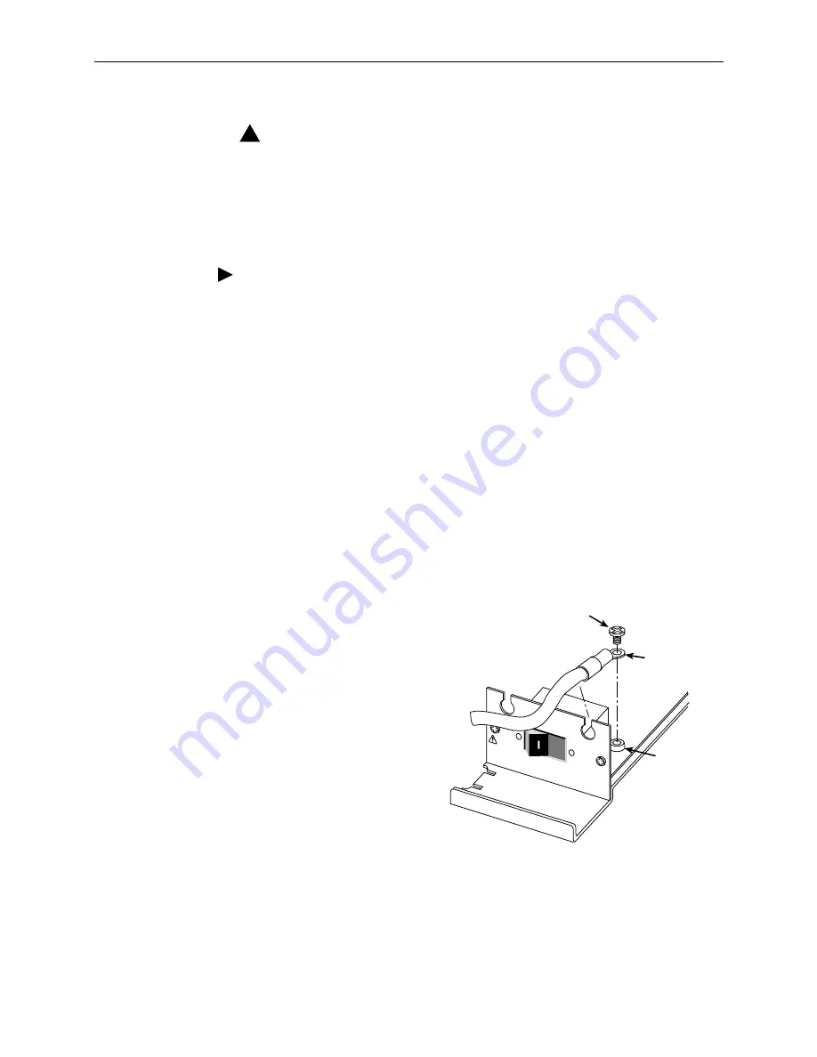
3. Remove the two M4 Phillips-head screws installed in the power taps located
on the left and right side of the PEM wiring board. Also remove the two split
cable bushings from the PEM faceplate if they are installed.
4. Fasten the #8 AWG wires, with their ring tongue terminals properly installed
(see
), to the power taps using the M4 Phillips-head screws.
— Connect the –48V wire to the power tap on the right (48V NEG is printed
on the front of the PEM’s faceplate).
— Connect the 48V RTN (return or +) wire to the power tap on the left
(48V RTN is printed on the front of the faceplate).
Tighten the M4 screws
securely to the power taps
while keeping the ring
tongue terminals and their
wires dressed parallel to the
board and perpendicular to
the faceplate.
5. Feed and dress the power
wires through the notched
holes at the top of the
PEM’s faceplate.
6. Slightly spread open the
split cable bushings and slip
them over the wires and
into the holes at the top of
the faceplate. Press on the
cable bushing to snap it into
the faceplate.
7. Reinstall the PEM into the chassis using the mounting screws removed in
8. Repeat the above steps for the remaining PEM.
9. Cable ties may be used to secure the power wiring to the PEM brackets.
00-16713
48V R
T
N
48V NEG
POWER ENTR
Y M
ODULE
LEFT UNIT
: LINE A
RIGHT UN
IT: LINE B
WARNING!
POWER MUST BE DISCONNECTED A
T THE SOURCE
BEFORE REMO
VING OR INST
ALLING
THIS PW
R ENTR
Y MODULE
O
Ring Tongue
Terminal
M4 Phillips-head
Screw
Power Tap


