Wireless Data Gateway
1-2
November 1996
3981-A2-GN31-20
Logical Description
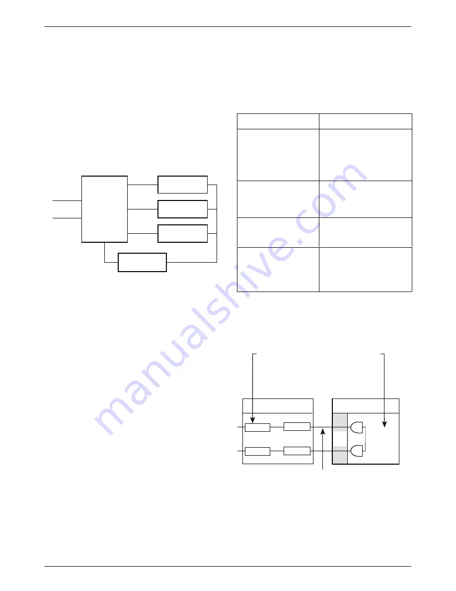
The WDG consists of three major functional areas:
•
Network/Switch Interface
•
Modem Banks
•
Network Management
See Figure 1-2.
Network
Interface
Network
Management
4-Wire
E&M
T1 or E1
Modem Bank
Modem Bank
Modem Bank
496-14618-01
Figure 1-2. WDG Functional Areas
Network/Switch Interface
The Network/Switch Interface terminates two digital
T1 or E1 signals from the loop-around connections of a
mobile switch and provides a 4-wire E&M signaling
interface to the modem banks.
The interface is implemented using the ACCULINK
Access Controller (AAC).
•
The CSU WAN modules on the AAC terminate the
T1 signals.
•
The bus architecture of the AAC routes individual
DS0 slots of the T1 to a 4-wire analog interface on
4-wire E&M interface cards within the AAC.
•
Each pair of E&M ports map to a time slot on the
T1 looparound trunks.
•
Each 4-wire E&M card provides 8 analog interfaces
in the form of a 50-position connector.
Modem Bank
The modem bank terminates 4-wire E&M signals from
the Network/Switch Interface with paired analog modems
in a carrier. Modems are either idle or active.
When . . .
Then . . .
When two paired
modems are idle
The modems act as an E&M
pass-through circuit.
Transmit signals from one
E&M port on the AAC are
routed to the receive path of
the next E&M port.
When fax calling tone is
detected
The detecting modem
signals its partner not to
answer. The modems are in
fax pass-through mode.
When a modem goes
active (detects answer
tone)
It signals its partner modem
and they begin training.
When both modems are
active
The pass-through function is
disabled and the modems
terminate the signals from
the E&M ports on the AAC.
See Figure 1-3.
T1 or E1 signal
enters here from
the switch's
looparound trunks.
A single DSO
(shown here as
TS1) is brought
out and bussed to
a port on the
4-wire E&M card.
The 3811
Plus
modems
terminate the
modem signal
from the cellular
modem and
route the data to
another modem
through a DTE
crossover cable.
The signals between
the Network Interface
block and the Modem
Bank use a 4-wire E&M
signaling arrangement.
Network
Interface Block
Modem Bank
DTE
Crossover
Cable
4W
NIM
4W
E&M
TS1
TS1
3811
Plus
E&M1-1
E&M1-2
WAN2
WAN1
3811
Plus
496-14619-01
Figure 1-3. Gateway Channel


