Assembly Instructions
ASSEMBLY INSTRUCTIONS
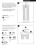
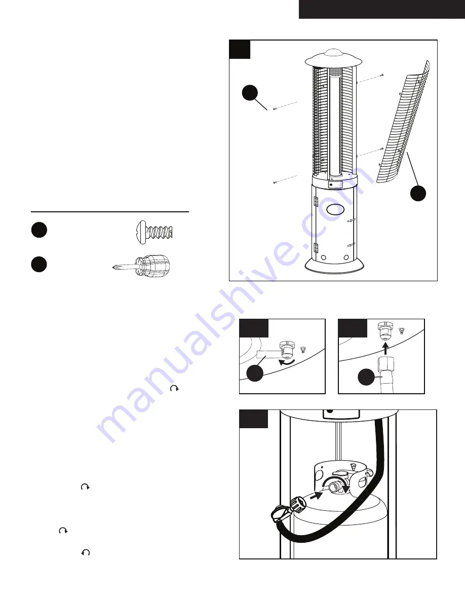
Hardware Used
MM
MM
D
x 1
2
x 1
PP
Philips
screwdriver
Screw
M5×10 mm
9
10
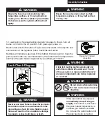
any high temperature surfaces, or it may melt
WARNING! Ensure the hose does not contact
10
. Install regulator to the heater.
.
secure it with all (1
2
) of the M5×10
screws
in to their original support slots accordingly.
hanging it on the upper support slots.Next tightly
9
.Re-install the protective steel guard(D) by
and leak, causing a fire.
11
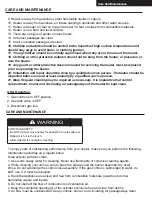
10. Wrap gas intake with teflon tape (TT)
in clockwise direction (fig. 10-A).
Then connect gas hose (H) (fig. 10-B)
The knob on the LP tank must be closed.
Make sure that the knob is turned clockwise
to a full stop. The cylinder supply sysem must
be arranged for vapor withdrawl. Check that
the control knob on the control unit is turned
off. Hold old the regulator in one hand and
insert the nipple into the valve outlet. Be sure
the nipple is centered in the valve outlet. The
coupling nut connects to the large outside
threads on the valve outlet. Hand-tighten the
coupling nut clockwise until it comes to a full
stop. Firmly tighten by hand only. (fig. 10-C)
To Disconnect: Fully close the tank by
turning clockwise until the regulator
assembly detaches clockwise. Turn the
coupling nut counterclockwise.
10-A
10-B
10-C
H
TT
Summary of Contents for OH-R744B
Page 19: ...5016039...


