background image

 Form 14-11-00-00 version 10

© 20

19

 Paragon Pro Manufacturing Solutions All Rights Reserved.

O P E R AT O R ’ S   M A N U A L

MADE IN USA BY

Adjusta ble Wor k Platfor m

®

For Models

1101 & 1101-96

(Model 1101 illustrated in this manual)

Before operating this equipment, thoroughly read this set of instructions, make sure you 

understand them, and only then follow the step-by-step directions. Failure to do so could 

result in serious property damage and / or serious bodily injury or death.

Read and become familiar with this manual BEFORE operating unit.


WARNING

Summary of Contents for Tele-Tower 1101

Page 1: ... 1101 1101 96 Model 1101 illustrated in this manual Before operating this equipment thoroughly read this set of instructions make sure you understand them and only then follow the step by step directions Failure to do so could result in serious property damage and or serious bodily injury or death Read and become familiar with this manual BEFORE operating unit WARNING ...

Page 2: ...ct We take pride in providing the best for our customers Quality innovation and excellence are all qualities this company ensures No product is sent without being factory tested and inspected to ensure the highest quality for you It all began in 1972 when Roland Young designed our first product the PANELLIFT Brand Drywall Lift and revolutionized the drywall industry To this day we are continuously...

Page 3: ... 3 Care Maintenance Page 4 Assembly Pages 5 7 Operation Pages 8 9 ASME Standards for Wire Rope Page 10 Parts Index Pages 11 12 Safety Information Page 13 CONTENTS This manual covers TELE TOWER Adjustable Work Platform Models 1101 and 1101 96 NOTICE All contents of this manual are copyrighted and nothing may be reprinted in whole or in part without prior written permission iii ...

Page 4: ...er or outside the guard rail system to access work Over extending can create a fall hazard DO NOT extend the length or width of the Tele Tower Adjustable Work Platform beyond the manufacturer s supplied design DO NOT lay decks planks or any other form of staging or platform across the toe boards of the Tele Tower Adjustable Work Platform Damage to the toe boards may result making the Tele Tower un...

Page 5: ...four ladder lock pins are fully engaged and the cable is prop erly strung and taut under the sheaves the base outriggers are extended to maintain a height to base ratio in keeping with applicable federal state and local stan dards all four casters are securely installed with bolts and brakes are set and properly functioning all guardrails chains and anti sway braces are correctly and securely inst...

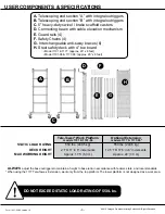
Page 6: ...the top platform The lower platform is not designed as a work area ALWAYS adjust the base outriggers to maintain a height to base ratio in accordance with federal state and local standards A Telescoping end section A with integral outriggers B Telescoping end section B with integral outriggers C 5 heavy duty swivel brake scaffold casters D Connecting beam with cable elevation mechanism E Guard rai...

Page 7: ...an this code to watch the video on your mobile device 4 The following general maintenance and care items shall be observed performed followed at a frequency determined by a designated Competent Person as defined by OSHA 29 CFR 1926 32 f to be appropriate based on usage patters specific to the deployment of the equipment by the owner Occasionally oil all spring pins and cable sheaves and ensure pro...

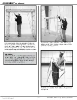
Page 8: ...n slot 3 Rotate winch handle counterclockwise and release cable from storage on beam 4 Place cable under sheave at lower end of each tele scoping ladder section 2 Engage ladder lock pins and lock one caster on end Section B Allow casters on Section A to roll while connecting to Section B Similarly secure as shown in step 1 Secure with bolt and wing nut 5 NOTE When disassembling loosen wing nut and...

Page 9: ...rate the Tele Tower Adjustable Work Platform without these braces Doing so can result in damage to the structure which can lead to failure that can result in severe prop erty damage and or severe bodily injury or death 7 Jog base of end sections to facilitate brace pin align ment DO NOT hammer on braces 8 For platform heights from 2 to 6 the deck may be placed on lower rungs For added safety use g...

Page 10: ... For deck heights of 6 or greater place the deck on the top rungs of the telescoping ladders and attach ALL FOUR deck braces between the deck and the base of the telescoping ladders Jog base of end sections to fa cilitate brace pin alignment DO NOT hammer on braces 7 WARNING NEVER use the Tele Tower Adjustable Work Platform at deck heights over 6 without these braces Doing so can result in damage ...

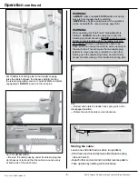
Page 11: ...ing the Tele Tower Adjustable Work Platform 2a TO ELEVATE DECK Retract and rotate the ladder lock spring pins to the disengaged position 2b Rotate winch handle clockwise until deck is 2 4 below the desired height 2c Return ALL FOUR ladder lock spring pins to the engaging position Rotate winch handle further until ALL FOUR ladder lock spring pins engage through the holes in the guide channels Opera...

Page 12: ...counterclockwise while the ladder lock pins are engaged Doing so will allow the cable to go slack which can cause the cable to wind unevenly on the winch tube This will cause the two telescoping ladders to move unevenly in relation to each other binding up in the telescoping frame and will hinder proper and safe locking of the ladder lock spring pins 9 3a TO LOWER DECK Be sure the cable passing un...

Page 13: ...ctual condition of the internal structure 00 General The use of cableways cranes derricks hoists hooks jacks and slings is subject to certain hazards that cannot be met by mechanical means but only by the exercise of intelligence care and common sense It is therefore essential to have personnel involved in the use and operation of equipment who are competent careful physically and mentally qualifi...

Page 14: ...aragon Pro Manufacturing Solutions All Rights Reserved PARTS INDEX Models 1101 1101 96 11 14 00 Model 1101 14 08 Model 1101 96 14 01 7 00 7 00 13 00 13 00 6 0A 6 0B 12 00 Model 1101 12 03 Model 1101 96 8 00 Model 1101 8 33 Model 1101 96 ...

Page 15: ... 2 washer 8 18 1 2 cap nut 8 19 Crank arm with fasteners 8 20 Winch Handle 8 22 Hanger bracket brake assembly 8 31 Beam body with sleeve bearings Model 1101 96 8 32 Winch tube Model 1101 96 8 33 Complete beam assembly for Model 1101 96 8 34 Cable Asmbly 1 8 x 31 3 with fasteners for Model 1101 96 9 00 Outrigger with stop bolt each total of 4 10 00 5 Caster brake mechanism fasteners ea total of 4 1...

Page 16: ...evelopmental 67 56 1 Trace Methylene Chloride Dichloromethane Cancer 75 09 2 Trace Nickel Cancer 7440 02 0 Trace Propylene glycol monobutyl ether Cancer 5131 66 8 Trace Toluene Developmental 108 88 3 Trace Wood Dust Cancer None Trace This product contains trace amounts of the following items which are known to cause These chemicals are not hazardous under product s intended use Please review CAS f...

Page 17: ......

Page 18: ......

Page 19: ......

Page 20: ...cturing Solutions All Rights Reserved Questions about assembly Can t find a part Need some other help Call us 1 800 448 0822 We ll get you set up Paragon Pro Manufacturing Solutions 7251 S 42nd St Grand Forks ND 58201 701 775 0551 www paragonpromfg com ...

Reviews: