
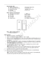


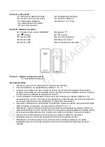


Part A-Positive LCD
A1: Radio Controlled icon A6: Outdoor Temperature
A2: Hours and minutes of Time A7: Alarm2 icon
A3: Indoor Temperature A8: Alarm1 turn on icon
A4: Calendar A9: DST Icon
A5: Day of the week
Part B
– Buttons and Framework
B1: “SNOOZE” touch position B2: “ ” button
B3
: “ ” button B4: “▲” button
B5
: “▼” button B6: “ ” button
B7:
“ ” button
B8: Hanging hole
B9: Support frame B10: Battery compartment
Part C
–Wireless Remote Sensor:
C1: Battery compartment
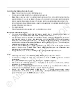
Initial operation:
•
Open the clock battery compartment cover
•
Insert 2 x AA batteries observing polarity [ “+” and “-” marks]
•
When you insert the batteries, all the icon on the LCD display will briefly light up for 3
seconds, and you will hear a beep tone,
At the same time into work mode
,
and detect indoor
temperature.
•
The Main Unit will now start to make a connection to the Remote Sensor. This operation
takes about 3 minutes and is displayed by a flashing reception RF antenna symbol in the
“OUTDOOR” display area on the receiver.
•
This now, replace Wireless Remote Sensor battery compartment cover Insert 2 x AAA
batteries observing polarity [ “+” and “–” marks]
Note:
The Main Unit searches for the synchronization signal of the outdoor remote sensor
for 3 minutes. Please let the remote sensor power on as much as possible within three
minutes to prevent the reception time from being missed.
•
After the main unit establishes a connection with the remote sensor, it will automatically
enter the radio control time reception mode.
Note:
If the Main Unit does not establish a link with the outdoor sensor, it will automatically
enter the receiving mode of the radio control time after 3 minutes.